Doc No. FM0804 issue 4 Page 44
24. DOOR ENTRY TELEPHONE INSTALLATION
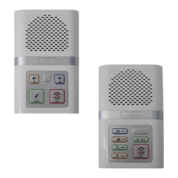
Audio to door signal (channel 1)
Audio to phone signal (channel 1)
Audio to door signal (channel 2)
Audio to phone signal (channel 2)
IMPORTANT: the Advent XT2 controller must be reset for it to detect a telephone handset has been connected.
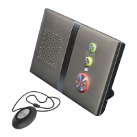
SECOND HANDSET
Normally only one telephone will be connected per intercom, if a flat requires a second extension handset then it is
simply connected in parallel with the first. The second handset must have its link LK1 moved to position B
(EXTENSION) - it is not possible to have more than 2 telephones per flat. Note: the Advent XT2 controller must be
reset for it to detect a second telephone handset has been connected.
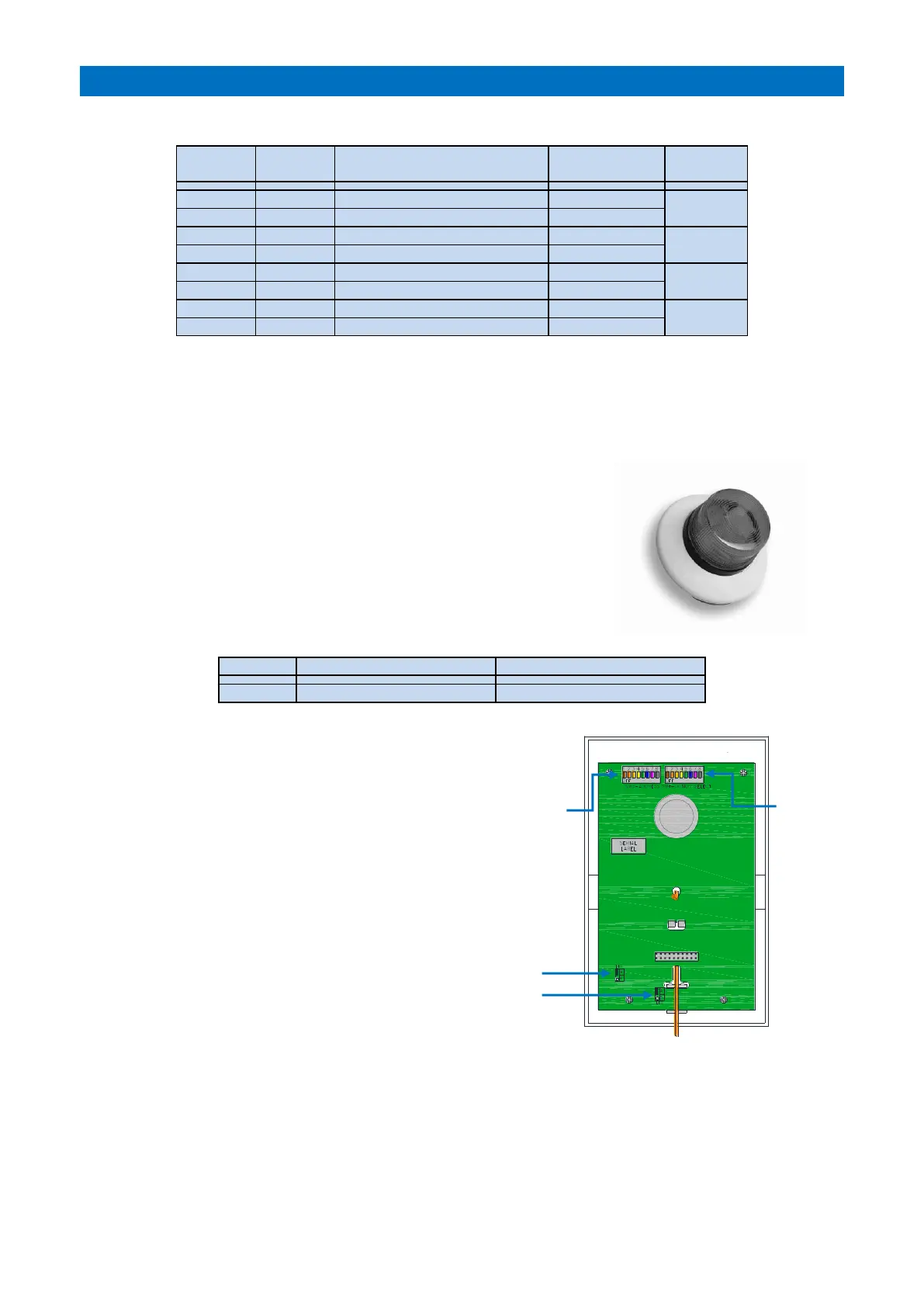
OPTIONAL HARD OF HEARING STROBE
Hard of hearing strobe lights (Tynetec P/No. ZSL047) can be connected to the
telephone STROBE - and STROBE + terminals.
The strobe will flash when the telephone is ringing.
TELEPHONE LINK SETTING
Link LK1 should be set in position A “MASTER” if there is only one telephone connected.
If a second telephone is connected, then its link must be set in position B “EXTENSION”.
EXTENSION (2nd handset only)
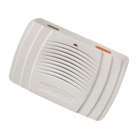
INTERCOM DIL SWITCH & LINK SETTINGS
The Address DIL switch must be set using an 8 bit binary
code starting from “1” - see section 14.
Set the Options DIL switch 3 ON when a door entry
telephone is connected.
Links LK1 & LK2 should both be in position A
unless an extension handset is connected – see section 14.
PROGRAMMING
The Privacy Time, No. of Ring Cycles and progressive door entry parameters must set in programming - see the
Tenants Door Entry section of the Advent XT2 Programming Manual (Doc No. FM0815).