EasyManua.ls Logo

typical TW1-571 - Circuit Diagrams; Reference List for the Circuit Diagrams

typical TW1-571
58 pages
Print Icon
To Next Page IconTo Next Page
To Previous Page IconTo Previous Page
Loading...
14
11.05
11.05.01
Circuit diagrams
Circuit diagrams
Reference list for the Circuit diagrams 91-191 524-95 and 91-191 534-95
Control package
P40 ED
91-191 524-95
A1
A2
A14
C1
H1
H10
HQ1
K1
M1
M10
PD3
Q1
R1
S1
S10
S41
S42
S43
S46
T10
X0
X1
X2
X2.1
X2.2
X3
X4
X5
X6
X7
X8
X22
X24
X25.0
X25.1
X25.2
X25.3
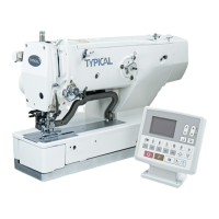
Control unit Typical P40ED
BDF-S2 control panel
Sewing head recognition(OTE)
Start capacitor
Sewing lamp
LED reverse stitch counting
-
Knife motor relay
Knife motor
Externer Positionsgeber PD3 (574)
Hauptschalter
-
Pedal (speed control unit)
Knife motor key
Manual backtacking key
Needle position change / threading key
Single stitch key
Start inhibitor switch
Knife motor transformer
RS 232 interface (PC) plug
Sewing motor plug
Incremental transmitter plug
Synchronizer PD3 plug
Pedal (speed control unit) plug
BDF-S1 control panel plug
Outputs/inputs plug
Bobbin thread monitor plug (optional)
Light barrier plug (optional
-
Thread trimmer plug(-900/..)
Automatic presser foot lift plug (-910/..)
Backtacking device plug (-911/..)
Backtacking device plug (-911/..) - roller presser
Backtacking device plug (-911/..) - feed wheel
Backtacking device plug (-911/..) - needle
-
Synchronizer PD3 plug
Light barrier plug (optional)
PicoTop control panel plug / RS232
(PC)
-
-
-
-
-
LED series resistor
-
Control lamp main switch
-
-
P44 PD-L
91-191 534-95
Control unit Typical P44PD
PicoTop control panel
-
-
Sewing motor with incremental transmitter
45

Table of Contents

Related product manuals