Transport, installation and acceptance
6.3.5.1 Voltage supply
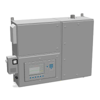
Fig. 6.5: Electrical connection, control unit (example)
Connect the combustion calorimeter to the voltage supply using connections 19,
20 – 21, 22 and PE (23, 24, 25 and 26) of the control unit in accordance with
national requirements.
Observe control unit operating instructions!
When making connection in terminal box of the control unit, observe the following:
Tightening torques, min/max min.: 0.3 Nm, max.: 0.4 Nm
Wire cross section, min/max rigid: 0.2 – 2.5 mm², flexible: 0.2 – 2.5 mm²
Use external protective conductor terminal (grounding bolt) on left side of housing!
Connect protective conductor firmly, secure against loosening. Protect connecting
parts effectively against corrosion, pay attention to suitable material. Cable cross-
section at least phase conductor cross-section.