17.8.1. Tool Direction Restriction
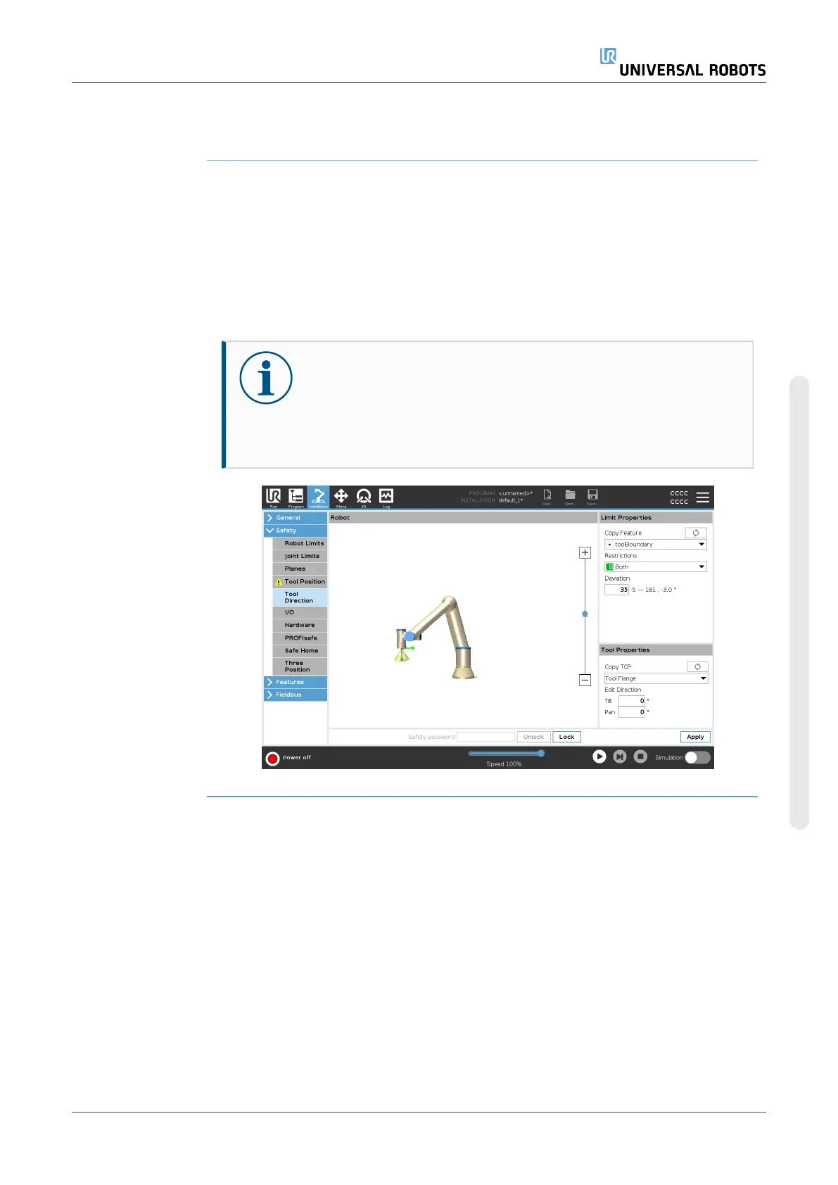
Description The Tool Direction screen can be used to restrict the angle in which the tool is pointing.
The limit is defined by a cone that has a fixed orientation with respect to the robot arm
Base. As the robot arm moves around, tool direction is restricted so it remains within
the defined cone. The default direction of the tool coincides with the Z-axis of the tool
output flange. It can be customized by specifying tilt and pan angles.
Before configuring the limit, you must define a point or plane in the robot installation.
The feature can then be copied and its Z axis used as the center of the cone defining
the limit.
NOTICE
Configuration of the tool direction is based on features. We
recommend you create desired feature(s) before editing the safety
configuration, as once the Safety Tab has been unlocked, the robot
arm powers off making it impossible to define new features.
User Manual 161 UR10e
Copyright © 2009–2024 by UniversalRobotsA/S. All rights reserved.