9.Stopping Time and Stopping Distance
Description You can set user-defined safety rated maximum stopping time and distance.
If user-defined settings are used, the program speed is dynamically adjusted to always
comply with the selected limits.
The payload CoG is at the tool flange.
The graphical data provided for Joint 0 (base), Joint 1 (shoulder) and Joint 2 (elbow)
is valid for stopping distance and stopping time:
•
Category 0
•
Category 1
•
Category 2
The Joint 0 test was carried out by performing a horizontal movement, where the
rotational axis was perpendicular to the ground.
During the Joint 1 and Joint 2 tests, the robot followed a vertical trajectory, where the
rotational axes were parallel to the ground, and the stop was performed while the robot
was moving downward. The Y-axis is the distance from where the stop is initiated to
the final position.
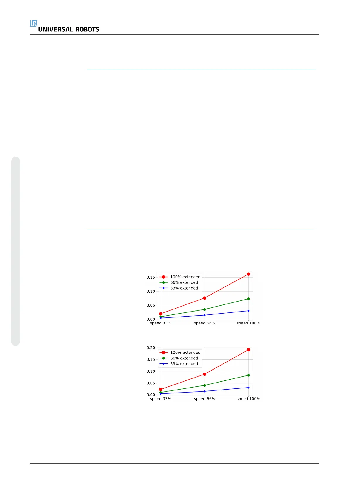
The values illustrated below represent two scenarios, robots with a maximum payload
of 10kg, and robots with a maximum payload of 12.5kg.
9.1. Robot Scenario 1: 10 kg.
Joint 0 (BASE)
Stopping distance
in meters for 33%
of 10kg
Stopping distance
in meters for 66%
of 10kg
UR10e 80 User Manual
9.Stopping Time and Stopping Distance
Copyright © 2009–2024 by UniversalRobotsA/S. All rights reserved.