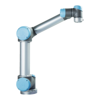
4.12. Robot Connections: Base Flange Cable
Description This subsection describes the connection for a robot arm configured with a Base
Flange Cable connector. For information on connecting a robot arm configured with a
fixed 6 meter Robot Cable, see 4.12 Robot Connections: Base Flange Cableabove.
Base Flange
Cable connector
The Base Flange Cable connector establishes the robot connection by connecting the
robot arm to the Control Box. The Robot Cable connects to the Base Flange Cable
connector on one end, and to the Control Box connector on the other end.
You can lock each connector when robot connection is established.
CAUTION
The maximum robot connection from the robot arm to the Control Box
is 6m. Improper robot connection can result in loss of power to the
robot arm.
•
Do not extend a 6m Robot Cable.
NOTICE
Connecting the Base Flange Cable directly to any Control Box can
result in equipment or property damage.
•
Do not connect the Base Flange Cable directly to the Control
Box.
UR10e 64 User Manual
4. Electrical Interface
Copyright © 2009–2024 by UniversalRobotsA/S. All rights reserved.
 Loading...


