EasyManuals Logo

Universal Robots UR10 Service Manual

Universal Robots UR10
123 pages
To Next Page IconTo Next Page
To Previous Page IconTo Previous Page
Page #13 background imageLoading...
Page #13 background image
All rights reserved 13 Servicemanual_UR10_en_3.1.3
3.1.4 General guidance to separate joint from counterpart
Disassemble:
1. Check if the necessary tools and documentation are available before starting a repair.
a. Service kit with torque tools, ESD Wristband, etc.
b. Thoroughly read and understand this guide.
2. Move the robot to a comfortable position for disassembly or if necessary dismount entire robot
arm from work cell and place on a solid surface.
3. Shut down the controller.
4. Remove blue lid.
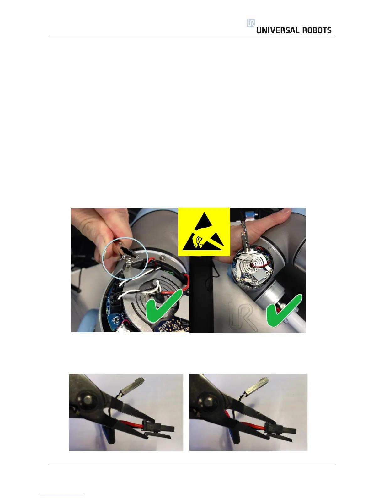
5. Reattach one of the screws from the blue lids, in order to connect an alligator Clip on the ESD
wristband as shown below.
6. Gently unplug the cable connectors without bending the printed circuit board.
The power supply connector for the size 1 has a lock that has to be engaged before it is pulled out
of the printed circuit board.

Table of Contents

Other manuals for Universal Robots UR10

Questions and Answers:

Question and Answer IconNeed help?

Do you have a question about the Universal Robots UR10 and is the answer not in the manual?

Universal Robots UR10 Specifications

General IconGeneral
Payload10 kg
Reach1300 mm
Degrees of Freedom6
Weight28.9 kg
Footprint190 mm diameter
Repeatability±0.1 mm
IP ClassificationIP54
ProgrammingPolyscope graphical user interface
Joint Range±360° on all joints
Power Consumption350 W
Communication InterfaceEthernet, Modbus TCP
Safety StandardsEN ISO 10218-1
Operating Voltage100-240 VAC, 50-60 Hz

Related product manuals