EasyManuals Logo

Universal Robots UR10 Service Manual

Universal Robots UR10
123 pages
To Next Page IconTo Next Page
To Previous Page IconTo Previous Page
Page #43 background imageLoading...
Page #43 background image
All rights reserved 43 Servicemanual_UR10_en_3.1.3
+
3.1.18 Joint spare part adaptation
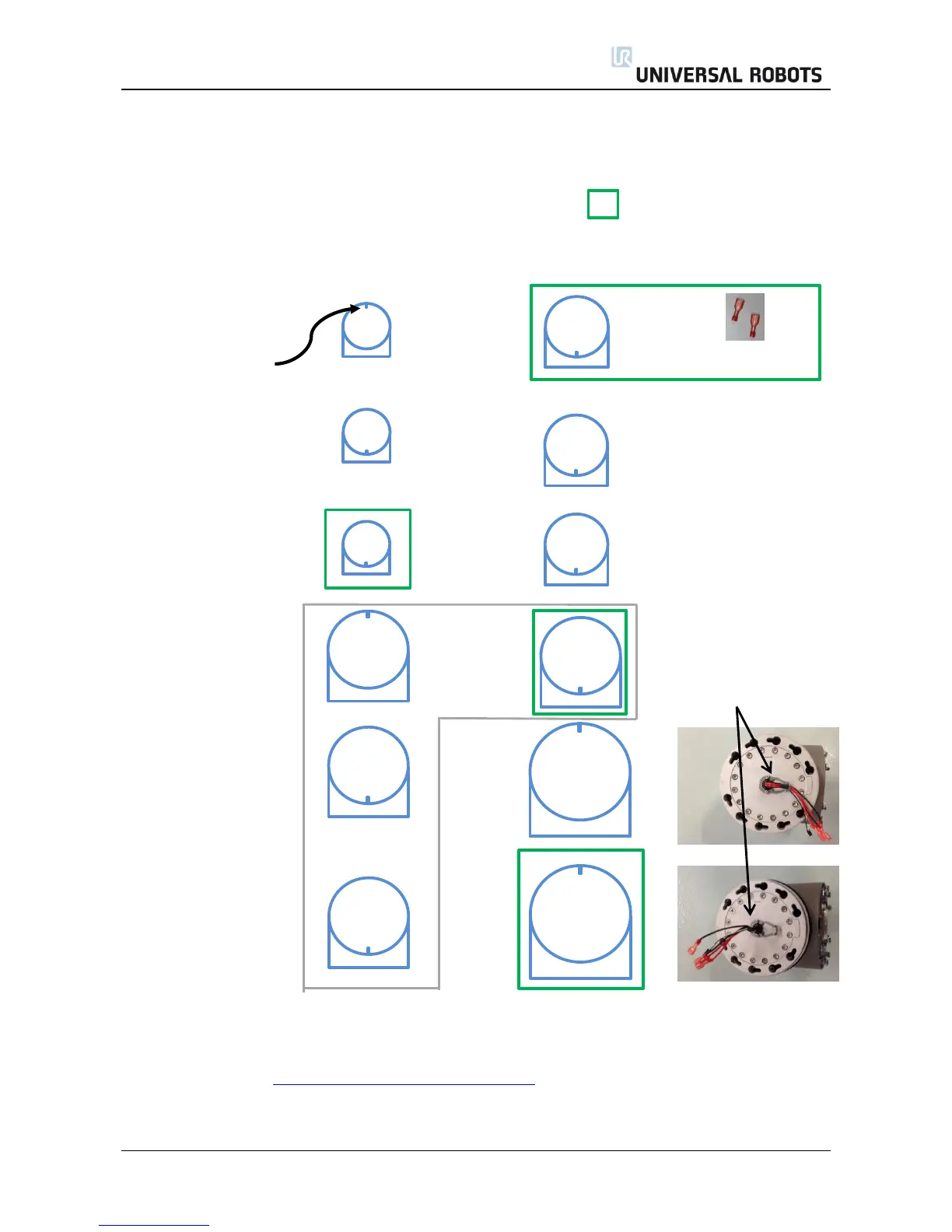
The UR5 and UR10 are constructed of 4 joint sizes and have to be setup on the robot:
Recommended spare joints for UR5 and UR10 are marked with:
Robot: UR5 UR10
Wrist 3: ID =5 Size 1* Size 2
Alignment screw or new wire bundle
Wrist 2: ID =4 Size 1 Size 2
Wrist 1: ID =3 Size 1 Size 2
Elbow: ID =2 Size 3* Size 3
Wires under/over bracket
Shoulder: ID =1 Size 3 Size 4
Base: ID =0 Size 3* Size 4
* Using a joint size in a different location i.e. UR5 base as UR5 Elbow, it may be necessary to change ID,
connect all joints electrically, turn the joint 180 degrees in low level control by using the Move tap's
Up/Down function, before mechanical assemble the robot. The robot then needs to be zero positioned or
dual robot calibrated - 3.1.15 Instructions for calibrating a joint

Table of Contents

Other manuals for Universal Robots UR10

Questions and Answers:

Question and Answer IconNeed help?

Do you have a question about the Universal Robots UR10 and is the answer not in the manual?

Universal Robots UR10 Specifications

General IconGeneral
Payload10 kg
Reach1300 mm
Degrees of Freedom6
Weight28.9 kg
Footprint190 mm diameter
Repeatability±0.1 mm
IP ClassificationIP54
ProgrammingPolyscope graphical user interface
Joint Range±360° on all joints
Power Consumption350 W
Communication InterfaceEthernet, Modbus TCP
Safety StandardsEN ISO 10218-1
Operating Voltage100-240 VAC, 50-60 Hz

Related product manuals