EasyManuals Logo

Universal Robots UR10 Service Manual

Universal Robots UR10
123 pages
To Next Page IconTo Next Page
To Previous Page IconTo Previous Page
Page #37 background imageLoading...
Page #37 background image
All rights reserved 37 Servicemanual_UR10_en_3.1.3
9. Zero position illustrations
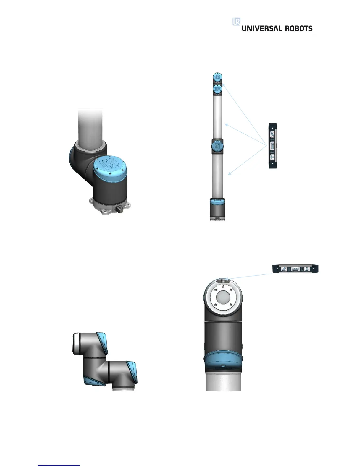
Base: Shoulder, Elbow, Wrist 1:
Base zero position is aligned so that the Shoulder, Elbow and Wrist 1 zero output flange is
output flange is offset 180 degrees from vertical aligned (if Base if horizontal).
the cable in back of robot base. Make sure that base of robot is horizontal, use
spirit level to align joints.
Wrist 2: Wrist 3:
Wrist 2 zero position is aligned similar Wrist 3 zero position is aligned so tool connector
to Base joint, with tool flange parallel is pointing upward.
with wrist Mount two bolts in tool holes and use spirit level
to align joint.

Table of Contents

Other manuals for Universal Robots UR10

Questions and Answers:

Question and Answer IconNeed help?

Do you have a question about the Universal Robots UR10 and is the answer not in the manual?

Universal Robots UR10 Specifications

General IconGeneral
Payload10 kg
Reach1300 mm
Degrees of Freedom6
Weight28.9 kg
Footprint190 mm diameter
Repeatability±0.1 mm
IP ClassificationIP54
ProgrammingPolyscope graphical user interface
Joint Range±360° on all joints
Power Consumption350 W
Communication InterfaceEthernet, Modbus TCP
Safety StandardsEN ISO 10218-1
Operating Voltage100-240 VAC, 50-60 Hz

Related product manuals