3.3. Securing the Robot Arm
Description
120
10
8 FG8
+
+
0.030
0.008
8.5 min.
8 FG8
+
+
0.024
0.006
x 13
8.5 min.
4 x
8.4
170
45°
S
2x 5
±1
Surface on which the robot is fitted
0.05
D
E
F
C
1
2
3
4
B
A
3
2
1
5
C
D
4
6
7
8
A
B
A3
UL class
PROPRIETARY AND CONFIDENTIAL
THE INFORMATION CONTAINED IN THIS
DRAWING IS THE SOLE PROPERTY OF UNIVERSAL
ROBOTS. ANY REPRODUCTION IN PART OR AS A
WHOLE WITHOUT THE WRITTEN PERMISSION OF
UNIVERSAL ROBOTS IS PROHIBITED
REV.
TEL: +45 89 93 89 89 FAX: +45 38 79 89 89 WEB: universal-robots.com
APP.
Engineer:
SIZE
SHEET 1 OF 1
SCALE:1:2
DWG NO.
TITLE:
DATE
NAME
Revision History:
731470
EN AW-6082 T6
1470.15 g
2014-06-16
Flange Base UR10 G5
UNLESS OTHERWISE SPECIFIED:
Dimensions are in millimeters
RoHS compliant (PB free)
Cleaned for chips and oil
NAME
DATE
Drawing
Approved
TOLERANCE
SURFACE FINISH
TREATMENT
MATERIAL
WEIGHT
PROJECTION:
DATE
2014-06-16
+/- 0,1 mm +/- 0,5°
Ra 1,6
Anodized nature 10-20µ
jmi
Status change date:
Replace drawing:
-0,1
+0,3
-0,3
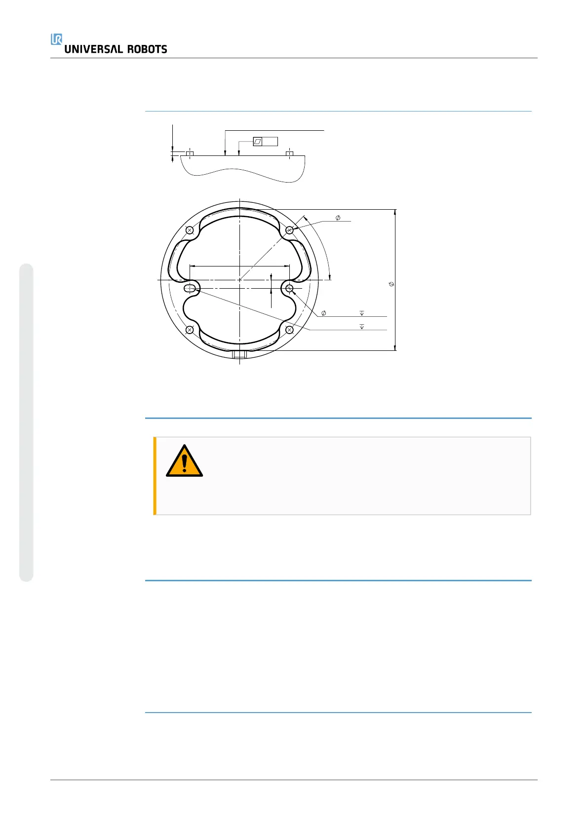
2.2:
Dimensions and hole pattern for mounting the
robot.
To power down
the robot arm
WARNING
Unexpected start-up and/or movement can lead to injury
•
Power down the robot arm to prevent unexpected start-up
during mounting and dismounting.
1. Press the power button on the Teach Pendant to turn off the robot.
2. Unplug the mains cable / power cord from the wall socket.
3. Allow 30 seconds for the robot to discharge any stored energy.
To secure the
robot arm
1. Place the robot arm on the surface on which it is to be
mounted. The surface must be even and clean.
2. Tighten the four 8.8 strength, M8 bolts to a torque of 20 Nm.
(Torque values have been updated SW 5.18. Earlier printed
version will show different values)
3. If accurate re-mounting of the robot is required, use the Ø8
mm. hole and Ø8x13 mm. slot with corresponding ISO 2338
Ø8 h6 positioning pins in the mounting plate.
UR10e PolyScope X 42 User Manual
3.Mechanical Interface
Copyright © 2009–2024 by UniversalRobotsA/S. All rights reserved.