EasyManua.ls Logo

Universal Robots UR3e User Manual

Universal Robots UR3e
361 pages
To Next Page IconTo Next Page
To Previous Page IconTo Previous Page
Page #304 background imageLoading...
Page #304 background image
Editing a Line The line appears as two points in your program tree. You must define each point.
1. In Installation, tap Features.
2. Under Feature, select Line to add a line to your program tree.
3. The line is made up of two points:
Tap one point to edit those coordinates, then tap the other line point to
edit those coordinates.
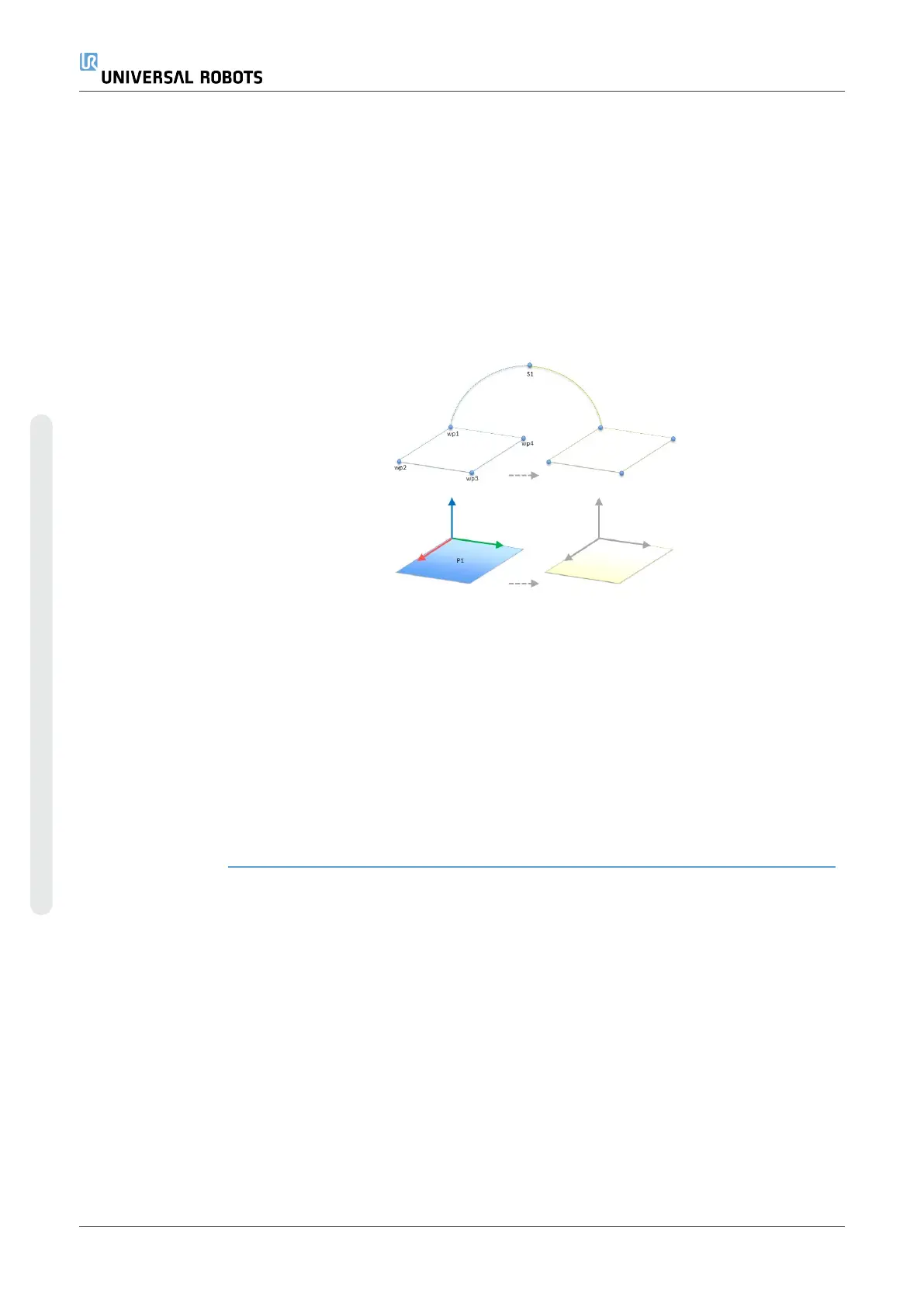
Editing a Plane
1. In Installation, tap Features.
2. Under Feature, select Plane to add a plane to your program tree.
3. Tap Edit to access the Edit screen to make changes to the positon and rotation
of the plane
20.14. Fieldbus
Description Here you can set the family of industrial computer network protocols used for real-time
distributed control accepted by PolyScope: MODBUS, Ethernet/IP and PROFINET.
20.14.1. MODBUS Client I/O Setup
Description Here, the MODBUS client (master) signals can be set up. Connections to MODBUS
servers (or slaves) on specified IP addresses can be created with input/output signals
(registers or digital). Each signal has a unique name so it can be used in programs.
Refresh Push this button to refresh all MODBUS connections. Refreshing disconnects all
modbus units, and connects them back again. All statistics are cleared.
Add unit Push this button to add a new MODBUS unit.
UR3e 304 User Manual
Copyright © 2009–2024 by UniversalRobotsA/S. All rights reserved.

Table of Contents

Other manuals for Universal Robots UR3e

Questions and Answers:

Universal Robots UR3e Specifications

General IconGeneral
Payload3 kg
Reach500 mm
Weight11.2 kg
Degrees of Freedom6
FootprintØ 128 mm
IP ClassificationIP54
Shoulder Rotation± 360°
Wrist 1 Rotation± 360°
Wrist 2 Rotation± 360°
Wrist 3 Rotation± 360°
Operating Voltage24 VDC
Power Supply100-240 VAC
Tool TCP Speed1 m/s
Base Rotation±360°
Programming MethodPolyscope graphical user interface
Communication InterfaceEthernet
Safety StandardsEN ISO 10218-1:2011
Repeatability±0.03 mm

Summary

Safety

2.1. Validity and Responsibility

Defines integrator responsibilities and system design compliance with standards.

2.4. General Warnings and Cautions

Lists essential safety practices for robot operation and personnel protection.

2.5. Intended Use

Specifies the robot's authorized industrial applications and limitations.

2.6. Risk Assessment

Outlines the legal requirement and methodology for performing risk assessments.

2.7. Pre-Use Assessment

Details mandatory tests that must be conducted before first use or after modifications.

2.8. Emergency Stop

Describes the function and reset procedure of the emergency stop button.

2.10. Safety-related Functions and Interfaces

Introduces built-in safety functions and I/O for connecting external devices.

Mechanical Interface

3.3. Securing the Robot Arm

Provides dimensions and hole patterns for securely mounting the robot base.

3.6. Maximum Payload

Details robot payload capacity and factors affecting acceleration.

Electrical Interface

4.1. Electrical Warnings and Cautions

General warnings for interface groups, especially regarding PLC safety signals.

4.3. Safety I/O

Describes dedicated safety inputs and configurable I/O for safety functions.

4.4. Three Position Enabling Device

Explains the connection and use of a three-position enabling device.

Maintenance and Repair

Stopping Time and Stopping Distance

Introduction

16.2. Robot Arm Installation

Guides through unpacking, mounting, and connecting the robot arm and control box.

16.4. Freedrive

Explains how to manually move the robot arm with released brakes.

16.6. Quick System Start-up

Provides steps for quickly starting up the robot.

16.8. Robot Cyber Security

Outlines principles and guidelines for securing the robot system.

16.9. Operational Mode Selection

Explains how to configure and switch between Manual and Automatic modes.

Software Safety Configuration

17.1. Setting a Software Safety Password

Guides on setting a password to unlock and protect safety settings.

17.2. Changing the Software Safety Configuration

Details the procedure for modifying safety settings according to risk assessment.

17.3. Applying a New Software Safety Configuration

Explains how changes take effect after applying and restarting the robot.

17.5. Software Safety Modes

Details Normal, Reduced, and Recovery modes for safety limit operation.

17.6. Software Safety Limits

Covers specifying safety system limits for robot behavior and violations.

17.7. Safety I/O

Explains the use of safety I/O signals for functions like E-stop and Reduced Mode.

17.8. Software Safety Restrictions

Details how to define safety planes to restrict robot workspace and movement.

Program Tab

Installation Tab

20.1. TCP Configuration

Explains how to define and configure Tool Center Points (TCPs) for robot tools.

20.2. Payload

Details setting payload, CoG, and inertia for optimal robot performance.

20.4. I/O Setup

Guides on defining I/O signals and configuring actions within the I/O tab.

Move Tab

21.1. Pose Editor Screen

Allows precise configuration of joint positions or TCP target pose.

Related product manuals