To secure the
robot arm
1. Mount the robot on a sturdy, vibration-less, surface that can withstand at least
ten times the full torque of the base joint and at least five times the weight of the
robot arm.
If the robot is mounted on a linear axis, or a moving platform, then the
acceleration of the moving mounting base is very low. High acceleration might
cause the robot to make a safety stop.
2. Tighten the bolts to 20Nm torque. (Torque values have been updated SW5.14.
Earlier printed version will show different values)
3. Use the two Ø8 holes provided, with a pin, to accurately reposition robot arm.
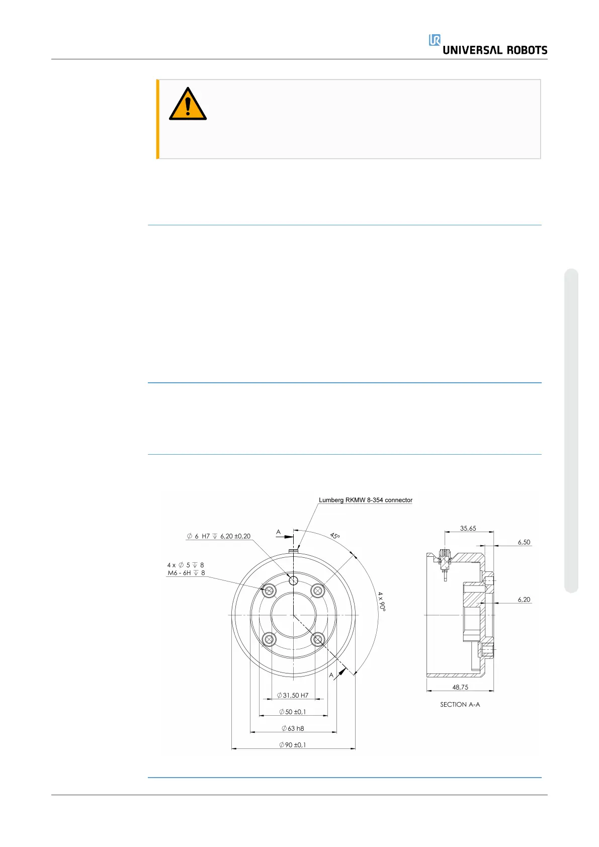
3.4. Securing Tool
Description The tool or workpiece is mounted to the tool output flange (ISO 9409-1) at the tip of the
robot. All measurements are in millimeters.
1.2:
Dimensions and hole pattern of the tool. All measurements are in millimeters.
Tool flange The tool output flange (ISO 9409-1) is where the tool is mounted at the tip of the robot. It
is recommended to use a radially slotted hole for the positioning pin to avoid over-
constraining, while keeping precise position.
CAUTION
Very long M8 bolts can press against the bottom of the tool flange and
short circuit the robot.
•
Do not use bolts that extend beyond 10mm to mount the tool.
User Manual 41 UR3e
3.Mechanical Interface
Copyright © 2009–2024 by UniversalRobotsA/S. All rights reserved.