3.3 Connect components to controller
Refer to the wiring diagram in the fold-out of this document.
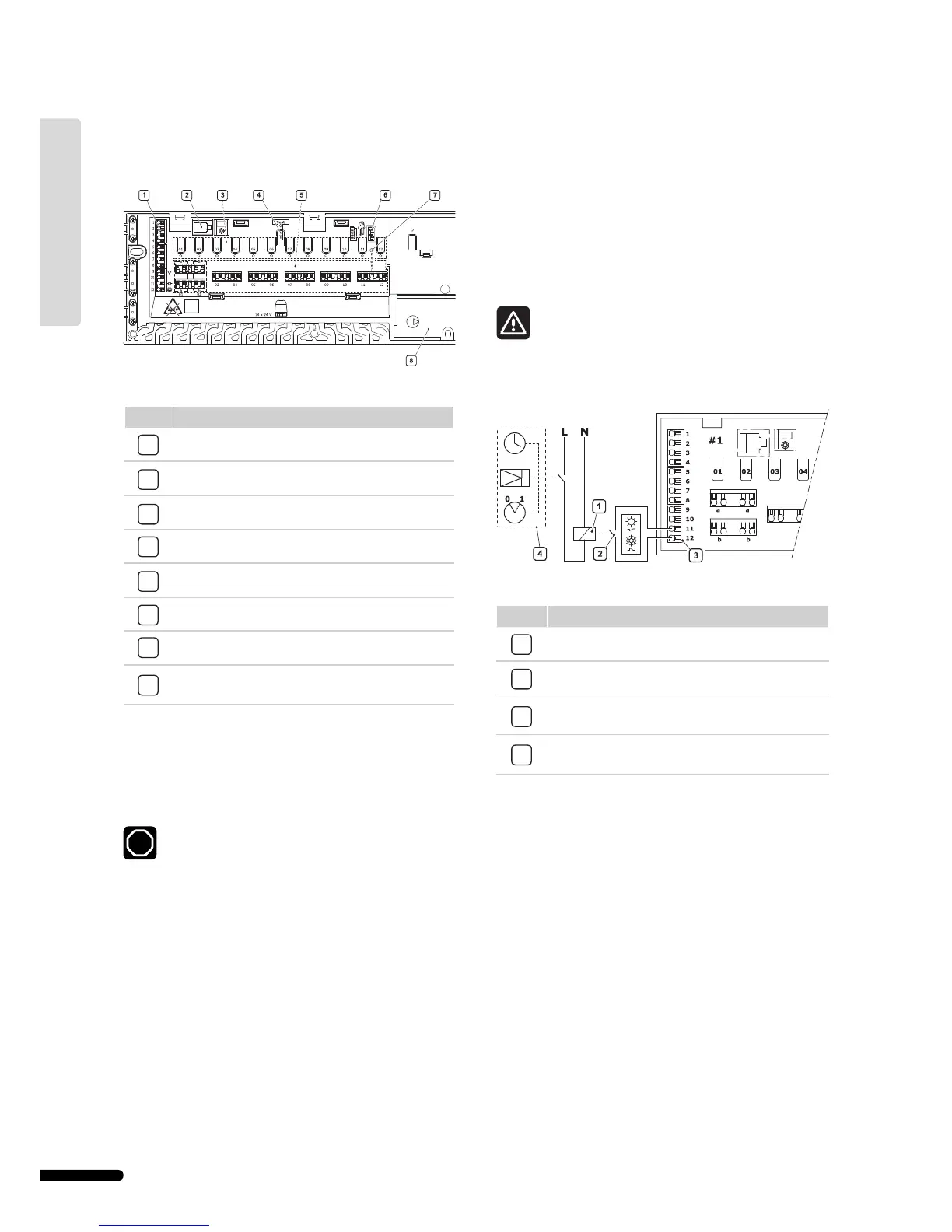
The illustration below shows the inside of Uponor Controller
C-55/56.
The list below describes the numbered items in the illustration.
Item Description
1
Terminal block for connecting antenna and options
2
Uponor Interface I-75/76 RJ-9 connector
3
Registration buttons and LEDs for channels 01 to 12
4
Test button and LED
5
Quick connectors for actuators
6
Socket for connecting data stick
7
Power LED
8
50 Hz 230 V AC power compartment and pump
management connection
Connect actuators to controller
Each thermostat can control one or more channels. To
simplify installation and maintenance, Uponor recommends
that actuators controlled by the same thermostat be wired in
sequence to the channels.
Identify the room supplied by each loop on the manifold
and determine which channel it must be connected to.
3.4 Optional: connect heating/cooling input
If the system is equipped with a cooling unit (requires additional
products), the Uponor Control System can manage the heating/
cooling switch input with the controller.
The heating/cooling input is controlled by a dry contact that
functions as either an auxiliary control system or two-position
relay.
• When the relay is open, the system is in heating mode.
• When the relay is closed, the system is in cooling mode.
To avoid damaging the Uponor Control System do not
apply a voltage across the Uponor Controller C-55/56
heating/cooling input.
The illustration below shows components of the heating/
cooling system.
The list below describes the numbered items in the illustration.
Item Description
1
Heating/cooling relay
2
Heating/cooling contact
3
Controller heating/cooling input (potential-free dry
contact)
4
Example of different type of heating/cooling relay
input
For further information, see the heating/cooling relay
documentation.