Example installation
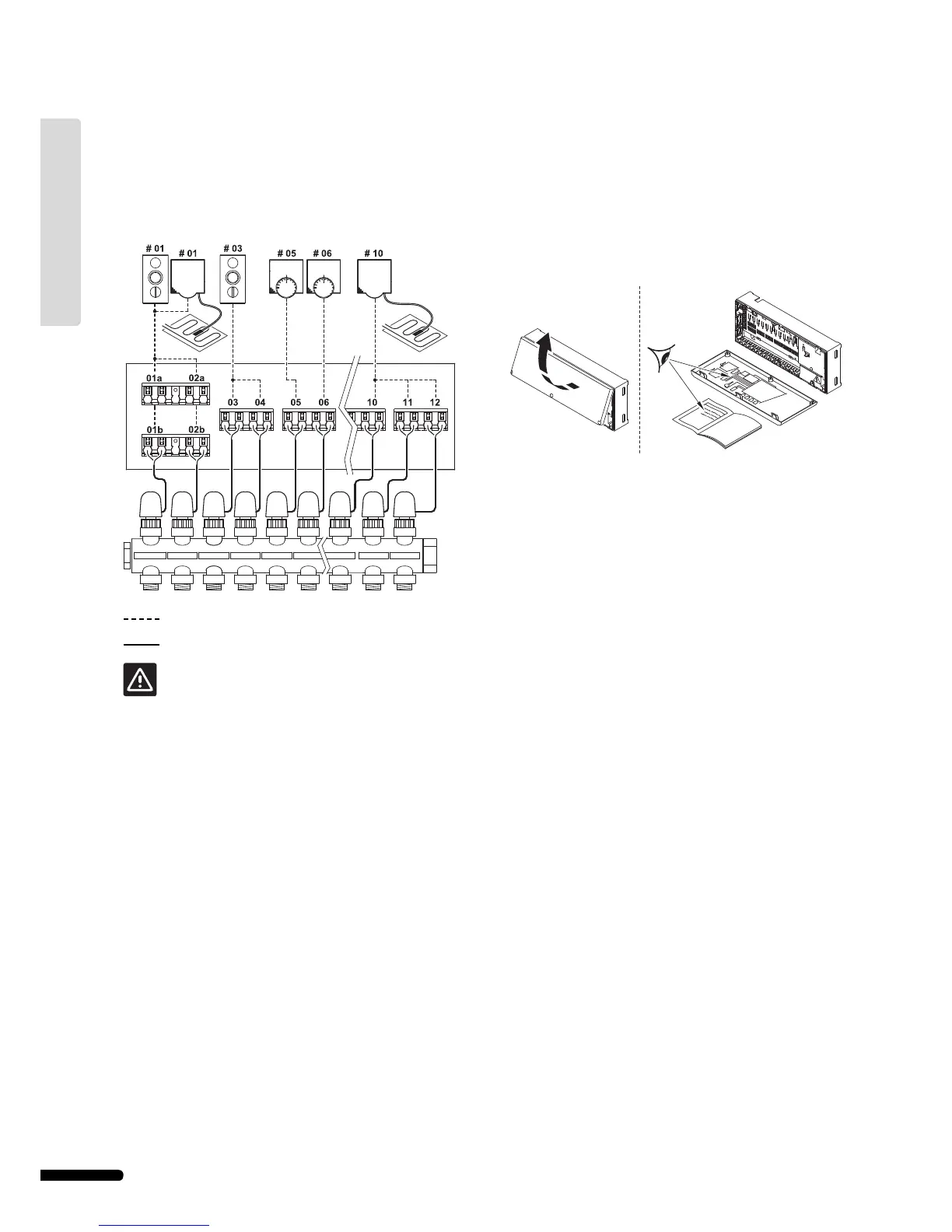
In the example installation illustrated below, the Uponor
Thermostat with display T-75 01 controls channels 01a, 01b and
02a, 02b. The external sensors attached to Uponor Thermostat
T-54 Public 01 and 10 communicate the fl oor temperature to
the Uponor Controller C-55/56. The Uponor Thermostat with
display T-75 03 controls channels 03 and 04.
: Radio/Program connection
: Cable connection
Note that only 24 V actuators are compatible with
Uponor Controller C-55/56.
2.1 Prepare for installation
Before installing the Uponor Control System:
• Check the contents of the packages against the packing list
to ensure that all components are present.
• Check if an external sensor is to be installed with Uponor
Thermostat T-54 Public.
• Study the wiring diagram in the fold-out or inside the
Uponor Controller C-55/56 cover.
To determine the best positions, following these guidelines:
• Install an Uponor Controller C-55/56 with antenna close to
each manifold.
• An AC power outlet is required to connect Uponor
Controller C-55/56 to power.
• Protect installation locations from running and dripping
water.
24 V 24 V
24 V
24 V
24 V
24 V 24 V 24 V
24 V
14
UPONOR CONTROL SYSTEM – INSTALLATION AND OPERATION MANUAL
UK English