12. Appendixes
Comfort Setting
By-pass
Main Menu
Information
Apply Holiday Mode
Start Date
Alarms
All Alarms
Battery Alarm
Cover Alarm
Operating Mode
Auto-balance
Supply Diagnostic
Access Level
Holiday Mode
End Date
Cancel Holiday mode
System
Rooms
Settings
Room List
Software Version
Holiday Temperature
(Set point)
Rooms
Room name
Min/Max
Temperature
Apply ECO Profi les
Disable Cooling
Edit ECO Profi les
System Parameters
Valve/Pump
Exercise
Cancel Exercise
Clock Settings
Date Format
Set Date/Time
Time Format
European Zone On
Fixed Date
Cancel Daylight Saving
Language
Valve/Pump
Exercise
Temperature Unit
Auto Daylight Saving
ECO Profi le List
Backlight
Modify Heating,
Cooling and range
Exercise Valve Only
Log Mode
Access Level
Supply Diagnostic
Auto-balance
Room Check
Cooling Available
Pump Management
Controller ID
Controller List
Controller List
Controller List
Controller List
Controller List
Room List
Room List
Room List
Room List
Room List
User Input
User Input
User Input
User Input
User Input
User Input
24 h or am/pm time
DD/MM/YYYY DD Mmm YYYY YYYY/MM/DD
YYYY Mmm DD
User Input
(Start + End)
User Input
User Input
(Day of week and time)
°C or °F
Always ON
Dimmed
(when inactive)
OFF (when inactive)
Basic
Advanced
User Input
(Day of week and time)
Auto Heating/Cooling Forced Heating Forced Cooling
Common or
Individual
Reset Controller ID Set Controller ID
§ 10.1
§ 9.19
§ 9.10
§ 9.11
§ 9.16
§ 9.15
§ 9.17
§ 9.14
§ 9.18
§ 9.5
or oror
§ 5.18
§ 5.17
Supply Water
Diagnostic Active
Room check
start/stop
Detailed
Long Term
§ 5.15
or
or
or
or
or
or
§ 5.16
§ 9.6
§ 9.12
§ 9.13
If cooling is
available
§ 9.16
§ 5.4
§ 5.8
§ 5.11
§ 5.7
Active
Inactive
or
or
§ 5.14
Controller List
Room List
§ 5.18
If more than one
controller is used
Without outdoor sensor
With outdoor sensor
With fl oor sensor
Clear Alarm List
or
Advanced access level
Installer access level
Basic access level
Only available in
advanced access level
Only available in
installer access level
Only applicable for
Uponor Interface I-76
Only available in
basic access level
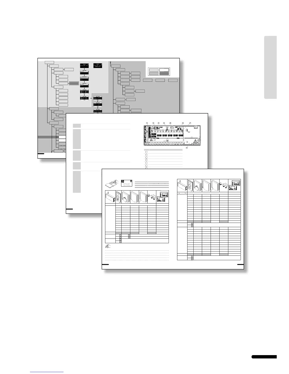
Menu description
Uponor Interface I-76
40
UPONOR CONTROL SYSTEM – INSTALLATION AND OPERATION MANUAL
41
UPONOR CONTROL SYSTEM – INSTALLATION AND OPERATION MANUAL
Technical data
Usable in all Europe 0682
Declaration of conformity:
We hereby declare under our own responsibility that products dealt with
by these instructions satisfy all essential demands linked to the R&TTE
1999/5/CE Directive dated March 1999.
General
IP IP30 (IP: degree of inaccessibility to active parts of the product and
degree of water)
Max. ambient RH (relative humidity) 95% max. at 20 °C
Thermostat
CE marking
Low voltage tests EN 60730-1* and EN 60730-2-9***
EMC (electromagnetic compatibility
requirements) tests
EN 60730-1 and EN 301-489-3
ERM (electromagnetic compatibility and
radio spectrum matters) tests
EN 300 220-3
Approval and certifi cation
KNX Konnex approval and certifi cation
Power Two 1.5 V AAA alkaline batteries
Voltage 2.2 V to 3.6 V
Operating temperature 0 °C to +45 °C
Storage temperature -10 °C to +65 °C
Radio frequency 868.3 MHz
Transmitter duty cycle 1%
Interface
CE marking
Low voltage tests EN 60730-1 and EN 60730-2-1
EMC tests EN 60730-1
Power 11 V DC ±10% from controller
Operating temperature 0 °C to +55 °C
Storage temperature -20 °C to +70 °C
Max. consumption 1 W
Antenna
Power supply 11 V DC ±10% from controller
Consumption less than 1 W
Radio Frequency 868.3 MHz
Transmitter duty cycle 1%
Receiver class 2
Controller
CE marking
Low voltage tests EN 60730-1* and EN 60730-2-1**
EMC tests EN 60730-1 and EN 301-489-3
ERM tests EN 300 220-3
Power 230 V AC +10/-15%, 50 Hz
Operating temperature 0 °C to +55 °C
Storage temperature -20 °C to +70 °C
Max. consumption 70 W
Pump relay output 230 V AC +10/-15%, 250 V AC 2 μA max.
Heating/cooling input Only dry contact
Valve outputs 24 V DC ±10%, 436 mA max. for outputs 1 and 2
24 V DC ±10%, 218 mA max. for outputs 3 to 12
Power connection 1 m cable with europlug
Pump connection wires 1.5 mm² max
Heating/cooling connection wires 1.5 mm² max
*) EN 60730-1 Automatic electrical controls for household and similar use
-- Part 1: General requirements
**) EN 60730-2-1 Automatic electrical controls for household and similar use
-- Part 2-1: Particular requirements for electrical controls for electrical
household appliances
***) EN 60730-2-9 Automatic electrical controls for household and similar use
-- Part 2-9: Particular requirements for temperature sensing controls
Item Description
1
Terminal block for connecting antenna and options
2
Uponor Interface I-75/76 RJ-9 connector
3
Buttons and LEDs from 01 to 12 for channel registration
4
Test button and LED
5
Quick connectors for actuators
6
Data stick connection
7
Power LED
8
50 Hz 230 V AC power compartment and pump management connection
42
UPONOR CONTROL SYSTEM – INSTALLATION AND OPERATION MANUAL
43
UPONOR CONTROL SYSTEM – INSTALLATION AND OPERATION MANUAL
Usa