11.6 Installer instructions
To determine if a problem is caused by the supply system or the control system, loosen the actuators from the manifold for the room
concerned, wait a few minutes and check if the fl ow pipe of the fl oor heating loop becomes warm.
If the pipe does not become warm, the problem is in the heating system. If the loop becomes warm, the cause could be the room control
system.
A supply system defect can be indicated by no warm water in the manifold. Check the boiler and circulation pump.
The products in this document might not be compatible with older versions of the Uponor Control System.
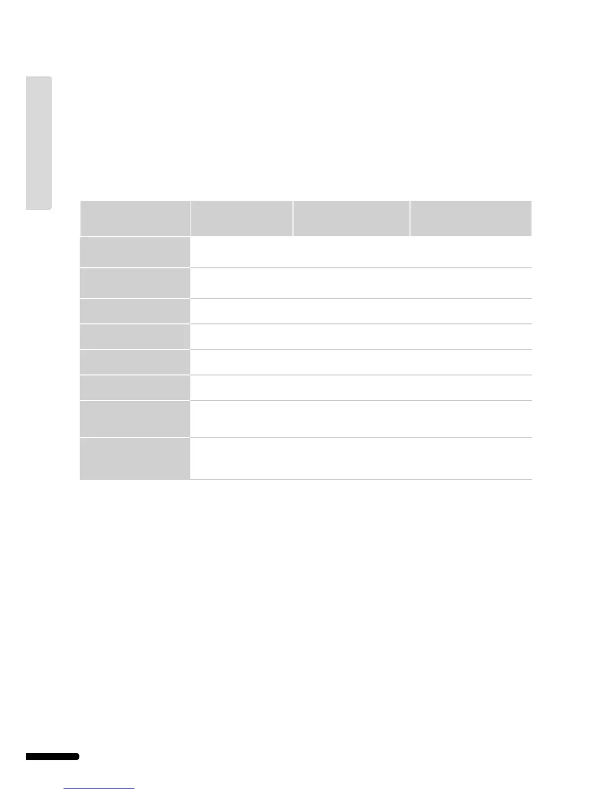
11.7 Technical specifi cations
Cables
Standard cable length
guaranteed without EMC
problems
Maximum cable length
guaranteed without any EMC
problems Gauge wire
Cable from controller to
antenna
0.30 m
3 m
25 m Controller: 0.2 mm² to 1.5 mm²
Antenna: Plug connector
Cable from controller to
interface
2 m
15 m
20 m Controller/Interface: 0.2 mm² to
1.5 mm² or plug connector
Cable from controller to
actuator
0.75 m 2 m Controller: 0.2 mm² to 1.5 mm²
Cable from controller to
controller
15 m 20 m Controller: 0.2 mm² to 1.5 mm²
External sensor cable to
thermostat
5 m 5 m 0.6 mm²
Floor sensor cable to
thermostat
4 m 4 m 0.75 mm²
Cable from relay switch to
controller heating/cooling
input
2 m 20 m Controller: 0.2 mm² to 1.5 mm²
Relay: 1.0 mm² to 4.0 mm²
Cable from external heating/
cooling controller to relay coil
10 m Can be extended up to 100 m
but must be checked by installer
External heating/cooling
controller: manufacturer-specifi c
Relay: 1.5 mm² to 4.0 mm²
46
UPONOR CONTROL SYSTEM – INSTALLATION AND OPERATION MANUAL
UK English