1. Uponor Control System
The Uponor Control System is a management system for
underfl oor heating systems. Comfort and temperature
control for each room can be combined through the various
components. Uponor Interface I-75 or Uponor Interface I-76
can be added to facilitate system optimization. Note that
Uponor Interface I-76 is compatible only with Uponor Controller
C-56, and Uponor Interface I-75 is compatible only with Uponor
Controller C-55.
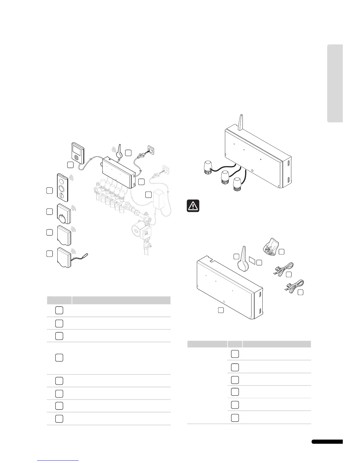
System example
The illustration below shows an Uponor Control System with
several installation options and thermostats.
The table below describes the components of a typical
installation. The item numbers correspond to the numbers in the
illustration.
Item Description
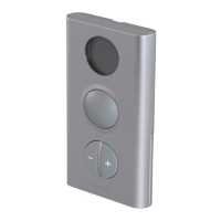
1
Uponor Thermostat with display T-75
2
Uponor Thermostat T-55
3
Uponor Thermostat T-54 Public
4
Uponor Thermostat T-54 Public with fl oor sensor.
The fl oor sensor is used for maximum or minimum
limitation of the fl oor temperature, regardless of
the room temperature. Uponor Thermostat T-54
Public can also be used with an outdoor sensor
5
Uponor Controller C-55/56
6
Uponor Antenna for controller C-55/56
7
Uponor Interface I-75/76
8
External connection box for pumps (third-party
product, just schematic example in illustration)
1.1 Controller C-55/56
The controller manages the operation of the actuators,
following a demand from the thermostats for heating or cooling,
according to Uponor Interface I-75/76 settings and temperature
information received from the thermostats. The controller is
typically located near the hydraulic system manifolds. The
illustration below shows the controller with actuators.
Observe that only 24 V actuators are compatible with
Uponor Controller C-55/56.
Components of Uponor Controller C-55/56
The illustration below shows the controller and its components.
The table below describes the components of the controller. The
item numbers correspond to the numbers in the illustration.
Component Item Description
Uponor Controller
C-55/56
1
Uponor Controller C-55/56
2
Antenna
3
Screws
4
Adhesive strips
5
0.3 m antenna connection cable
6
3 m antenna connection cable
7
1
3
2
4
6
5
8
1
3
2
4
6
5
24 V
24 V
24 V
9
UPONOR CONTROL SYSTEM – INSTALLATION AND OPERATION MANUAL
UK English