Hydraulic Schematic Section 4 - Schematics
Page 4-20 067448-023 LX31/LX41 Electric and Bi-Energy Work Platform | European Specifications
4-8 H
YDRAULIC
S
CHEMATIC
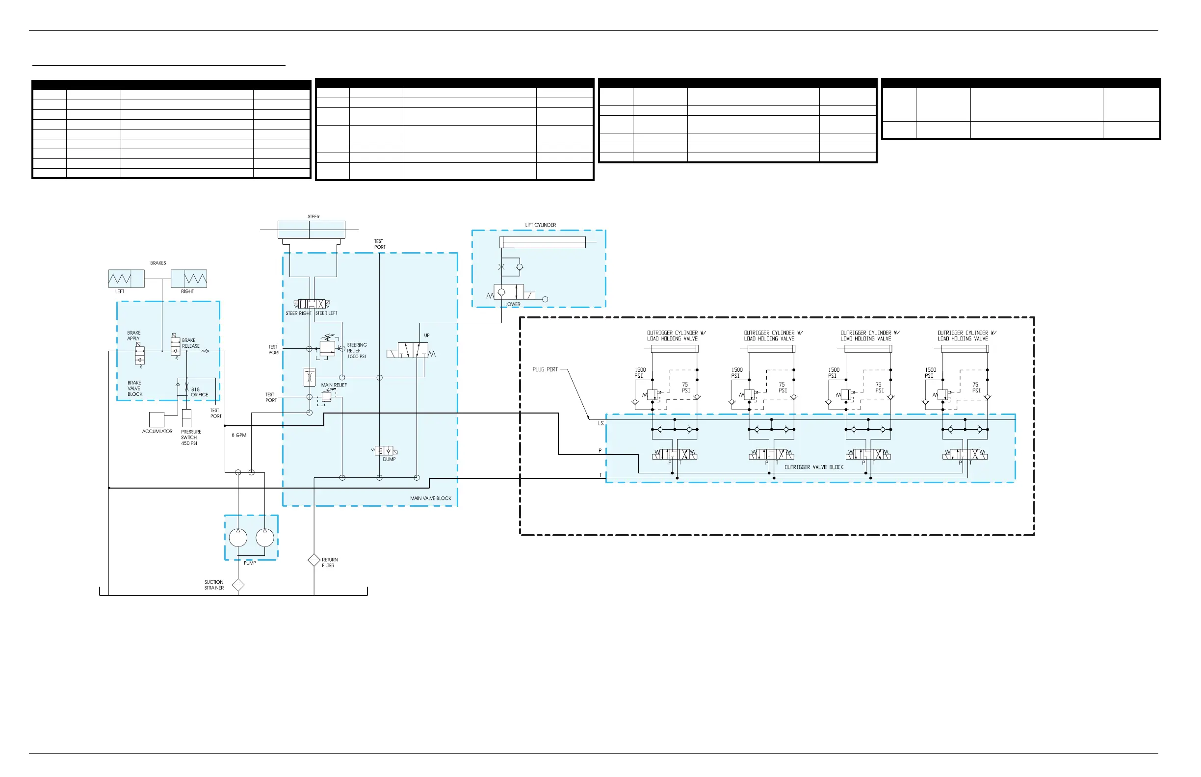
Table 4-7:
Hydraulic Schematic - 067446-000/067454-000
REFERENCE NAME FUNCTION LOCATION
ACC Accumulator Accumulate Hydraulic Fluid Brake Valve Block
CV1 Check Valve Slow Brake Release Brake Valve Block
BK1 Left Brake Apply Left Brake Pressure Left Brake
BK2 Right Brake Apply Right Brake Pressure Right Brake
CYL1 Cylinder, Lift Actuate Scissor Linkage to Lift Platform Chassis
CYL2 Cylinder, Steering Actuate Steering Linkage to Steer Front Wheels Chassis
CYL3-CYL6 Outrigger Cylinder Level and Support the Machine Chassis
LV1-LV4 Load Holding Valve Outrigger
F1 Filter, Return Filter Hydraulic Line Tank
F2 Filter, Tank Filter Contaminants Tank
FD1 Flow Divider Allows Lift and Steer Functions Together Main Valve Block
ORF1
Orifice, One-way,
Brake
Allow Brakes to Release Quickly and Apply
Slowly
Brake Valve Block
ORF2
Orifice, One-way,
Lift Cylinder
Limit Hydraulic Oil Flow at Lift Cylinder Lift Cylinder
P1 & P2 Hydraulic Pump Fluid Power for Hydraulic System Chassis
PS1 Pressure Switch Disable Machine Brake Valve Block
RV1 Valve, Main Relief
Over Pressure Protection for the Main Hydraulic
Line
Main Valve Block
REFERENCE NAME FUNCTION LOCATION
RV2
Valve, Steering
Relief
Over Pressure Protection for the Steering
Components
Main Valve Block
V1 Valve, Brake Apply Direct Hydraulic Oil to the Brake Cylinders Brake Valve Block
V2
Valve, Brake
Release
Release Hydraulic Oil Pressure from Brakes Brake Valve Block
V3 Valve, Steering Control Hydraulic Oil Flow to Steering Cylinder Main Valve Block
V4 Valve, Lift Control Hydraulic Oil Flow to Lift Cylinder Main Valve Block
V5 Valve, Dump Divert Excess Oil Main Valve Block
REFERENCE NAME FUNCTION LOCATION
V6 Valve, Down
- Hold Oil in Lift Cylinder when Deck is Elevated.
- Release Oil from Lift Cylinder to Lower Deck
- Has Cable Actuated Manual Override for
Emergency Lowering
Lift Cylinder
V7-V10 Valve, Outrigger Control Hydraulic Flow to Outrigger Cylinders
Outrigger Valve
Block
REFERENCE NAME FUNCTION LOCATION
BK1
BK2
V1
V2
ORF1
ACC
PS1
F2
P1
P2
F1
RV1
V5
FD1
RV2
V3
CYL2
CYL1
CYL3
LV1
V7 V8 V9 V10
LV2 LV3 LV4
CYL4 CYL5 CYL6
ORF2
V6
V4
CV1
OUTRIGGER OPTION
 Loading...


