Hydraulic Power Unit Section 2 - Service and Repair
Page 2-18 067448-023 LX31/LX41 Electric and Bi-Energy Work Platform | European Specifications
2-8 H
YDRAULIC
P
OWER
U
NIT
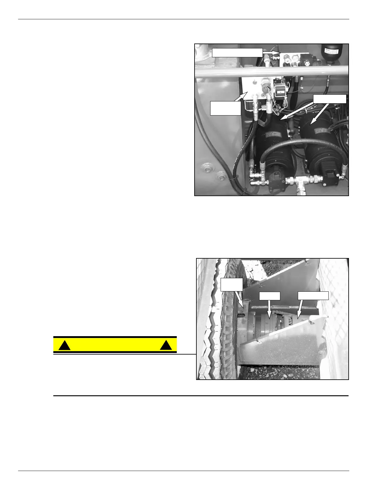
Figure 2-14:
Hydraulic Pump
R
EMOVAL
1. Mark, disconnect and plug the hose assem-
blies.
2. Mark and disconnect the electric cables.
3. Remove hardware which secures power unit
andremovefromchassis.
I
NSTALLATION
1. Install power unit using hardware previously
removed.
2. Unplug and reconnect the hydraulic hoses.
3. Reconnect the electric cables.
4. Fill the tank with clean hydraulic fluid.
5. Check the oil level in the hydraulic tank
before operating the work platform.
6. Operate the pump and check for leaks and
proper operation.
7. Replenish hydraulic fluid if necessary.
2-9 H
YDRAULIC
B
RAKES
Figure 2-15:
Rear Axle Assembly
R
EMOVAL
1. Park the work platform on firm level ground
and block the wheels to prevent the work plat-
form from rolling.
2. Disconnect and plug the hydraulic brake lines.
3. Tag and disconnect electric cables from drive
motors.
CAUTION
!
!
Clean all fittings before disconnecting the hose
assemblies.
Plug all port holes and hose assemblies
IMMEDIATELY to prevent contamination from
dust and debris.
4. Remove capscrews and washers holding the motor and brake to torque hub.
5. Remove the motor.
6. Remove the brake.
Brake
Manifold
Pump Motors
Hydraulic Manifold
Torque
Hub
Drive Motor
Brake

 Loading...


