Section 2 - Service and Repair Switch Adjustments
067448-023 LX31/LX41 Electric and Bi-Energy Work Platform | European Specifications Page 2-13
R
EMOVAL AND
I
NSTALLATION
,S
ERIAL
N
UMBER
4022-4274
WARNING
!
!
Never perform service while the platform is elevated without first blocking the elevating assembly.
DO NOT stand in the elevating assembly area while deploying or storing the maintenance brace.
1. Place the machine on a firm, level surface.
2. Deploy the maintenance brace (see “Blocking The Elevating Assembly” on page 2-8).
3. Disconnect the switch leads.
4. Remove the defective switch and install a new one.
5. Connect the switch leads.
6. Store the maintenance brace and lower the platform.
7. Adjust the Proximity Switch.
P
ROXIMITY
S
WITCH
A
DJUSTMENT
,S
ERIAL
N
UMBER
4022-4274
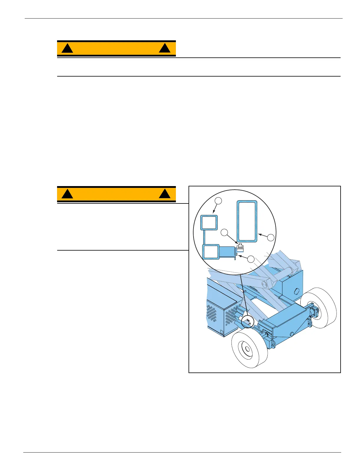
Figure 2-8:
Proximity Switch Adjustment - Serial Number 4022-4274
WARNING
!
!
Never perform service while the platform is
elevated without first blocking the elevating
assembly.
DO NOT stand in the elevating assembly area
while deploying or storing the maintenance
brace.
1. Place the machine on a firm, level surface.
2. Deploy the maintenance brace (see “Block-
ing The Elevating Assembly” on page 2-8).
3. Disconnect the switch leads and connect a
multimeter or continuity tester to the switch.
4. Place a reference mark on the switch
bracket to establish its position.
5. Store the maintenance brace and fully lower
the platform.
6. Measure and record the distance from the
top of the chassis to the base of the work
platform.
7. Elevate the work platform until the Proximity
Switch is OPEN (no continuity).
8. Measure the distance from the top of the
chassis to the base of the work platform and compare with Step 6..
• If the platform elevated 50 - 60 cm (1.75 - 2 ft.), no adjustment is necessary. Otherwise, continue.
9. Deploy the maintenance brace. Loosen the bracket adjustment screws and move the switch up to
increase or down to decrease the platform height. Tighten the adjustment screws.
10. Repeat Step 5. through Step 8..
1
3
2
4
1. Proximity Switch
2. Bracket
Adjustment
Screws
3. Inner Elevating
Assembly Tube
4. Chassis

 Loading...


