Section 2 - Service and Repair Hydraulic Manifolds
067448-023 LX31/LX41 Electric and Bi-Energy Work Platform | European Specifications Page 2-17
2-7 H
YDRAULIC
M
ANIFOLDS
Though it is not necessary to remove the manifold to perform all maintenance procedures, a determination
should be made prior to beginning as to whether or not the manifold should be removed before mainte-
nance procedures begin. Refer to the General Information Section for remove and replace instructions.
M
AIN
H
YDRAULIC
M
ANIFOLD
Refer to “Setting Hydraulic Pressures” on page 2-11 for adjustment instructions.
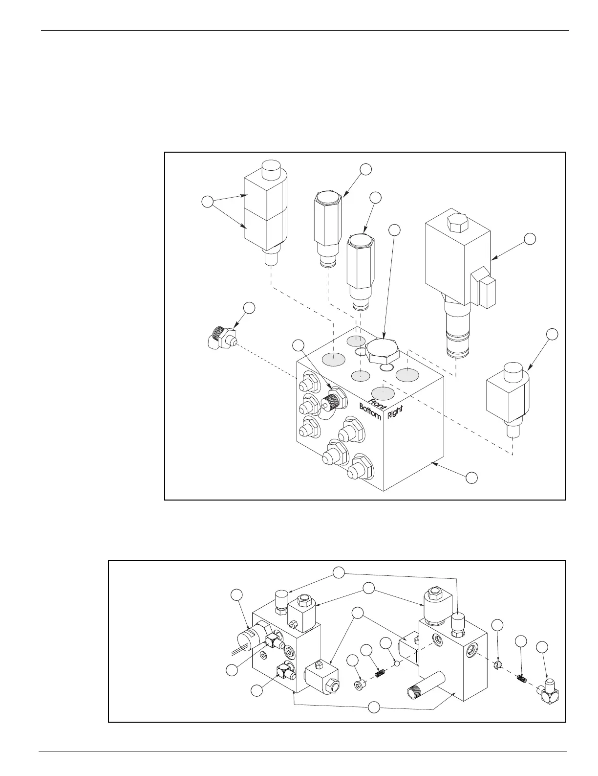
Figure 2-12:
Hydraulic Manifold
B
RAKE
H
YDRAULIC
M
ANIFOLD
Figure 2-13:
Brake Hydraulic Manifold
7
6
5
4
3
2
8
9
1
1 Valve Manifold
2. High Pressure Test Port
3. Lift Test Port
4. Flow Control Valve
5. Lift Relief Valve
6. Steering Relief Valve
7. Steering Solenoids
8. Lift Solenoid
9. Dump Valve
4
2
3
6
7
8
11
10
9
5
12
13
1
1 Valve Manifold
2. Gage Port
3. Valve, Normally Open
4. Valve, Normally Closed
5. Pressure Switch
6. Steel Ball
7. Spring, 6,4 mm
(0.25 in.) Diameter
8. Plug
9. Orifice
10. Spring, 9,5 mm
(0.375 in.) Diameter
11. 90° Fitting, 6MB-6MJ
12. 90° Fitting, 4MB-6MJ
13. 90° Fitting, 4MB-4MJ

 Loading...


