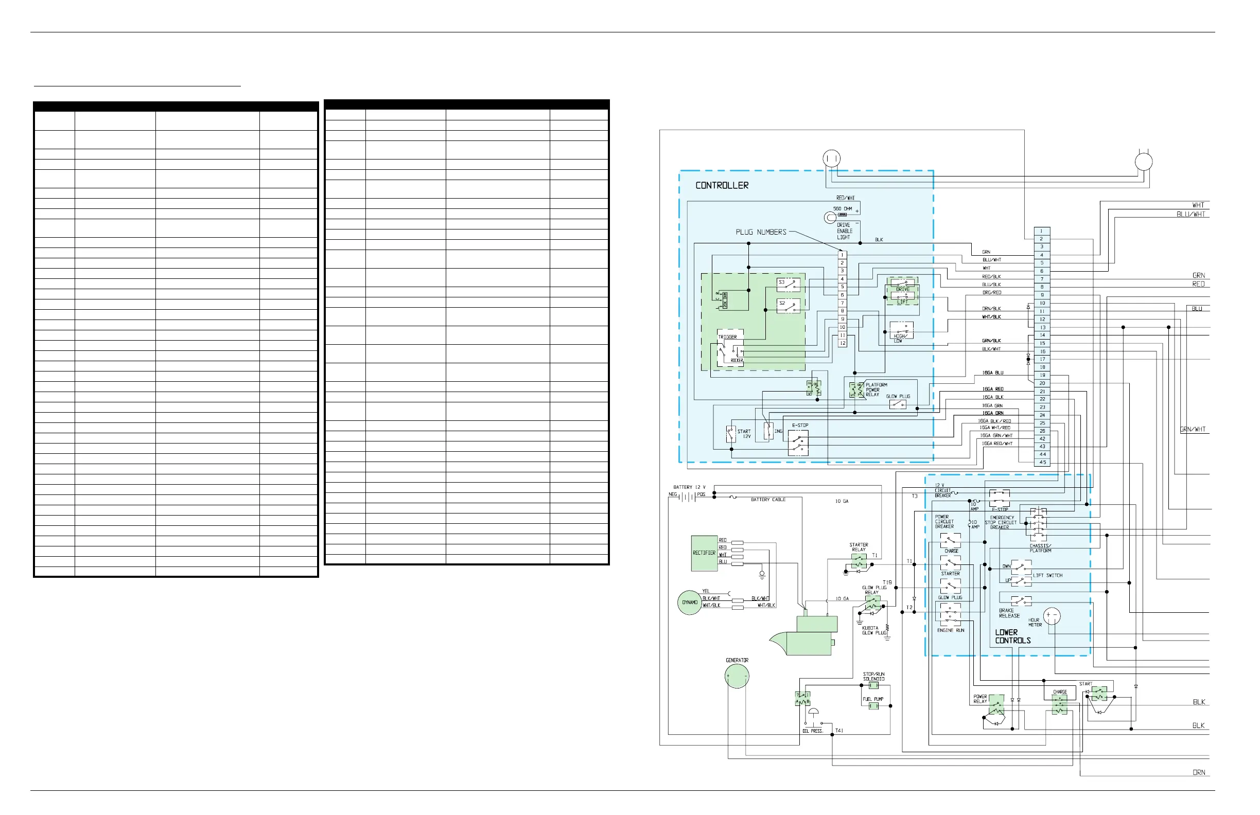
Electrical Schematic, LX Bi-Energy Serial # 4022-4274 Section 4 - Schematics
Page 4-2 067448-023 LX31/LX41 Electric and Bi-Energy Work Platform | European Specifications
4-1 E
LECTRICAL
S
CHEMATIC
, LX B
I
-E
NERGY
S
ERIAL
# 4022-4274
Table 4-1:
Electrical Schematic - 067447-002
REFERENCE NAME FUNCTION LOCATION
ALM1 Alarm, Level Sensor
Warning sound when machine is
off-level
Lower Control Box
ALM2 Alarm, Down
Warning sound when platform is
lowering
Lower Control Box
BAT1 48 VDC Battery Pack Electric Power Control Module
BAT2 12 VDC Battery Start Engine Control Module
C1 Main Power Contactor
Switch Power to All Solenoids and
Motors
Relay Panel
C2 Forward Contactor Switch Drive Motors to Forward Relay Panel
C3 Reverse Contactor Switch Drive Motors to Reverse Relay Panel
C4 Pump Override Contactor Override Pump Motors Relay Panel
C5 Pump/Traction Contactor
Switch Power
Between
Drive
Motors and Pump Motors
Relay Panel
CB1 Circuit Breaker Protect Emergency Stop Switch Lower Control Box
CB2 Circuit Breaker Protect Power Relay R9 Lower Control Box
CB3 Circuit Breaker Protect Engine Wiring Lower Control Box
CH1 Battery Charger Charge Batteries Control Module
CONT Controller Control Logic Module Relay Panel
F1 & F2 Fuse, Main Protect Circuit Wiring Relay Panel
F9 Fuse Protect Engine Wiring Control Module
GEN Generator Power Supply, Bi-Energy Power Module
L1 Drive Enable Light Indicate Power to Drive Circuit Upper Controls
M1 Hour Meter Record Operating Time Lower Control Box
MOT1 & 2 Electric Motor Drive Hydraulic Pump Power Module
MOT3 Electric Motor Drive Left Rear Wheel Chassis
MOT4 Electric Motor Drive Right Rear Wheel Chassis
MOT5 Starter Motor Start Engine Engine Module
P1 Fuel Pump Supply Fuel to Engine Engine Assembly
R1 Drive/Lift Relay Start Hydraulic Pumps Lower Control Box
R2 8 Meter Cutout Relay High Speed Drive Cutout Lower Control Box
R3 Level Sensor Alarm Relay Switch Power to ALM1 Lower Control Box
R4 Up Relay Switch Power to SOL1 & 2 Lower Control Box
R5 Down Relay Switch Power to SOL3 Lower Control Box
R6 Down Alarm Relay Switch Power to ALM2 Lower Control Box
R7 Steer Right Relay Switch Power to SOL5 Lower Control Box
R8 Steer Left Relay Switch Power to SOL6 Lower Control Box
R9 Pump Start Relay Power to S1 Lower Control Box
R10 Brake Relay Switch Power to SOL8 Lower Control Box
R11 Brake Release Relay Switch Power to SOL11 Lower Control Box
R12 Power Relay Switch Power to All Relays Lower Control Box
R13 Start Relay Start Engine Lower Control Box
R14 Charge Relay Charge Battery Pack Lower Control Box
R15 Brake Release Relay Power to Brake Relay R10 Relay Panel
R16 Platform Power Relay Power to Upper Controls Upper Controls
R17 Prevent Pump Start Relay Power to Pump Start Switch Upper Controls
R18 Starter Relay Power to Starter Motor Engine Assembly
R19 Glow Plug Relay Power to Glow Plug Engine Assembly
R20 Oil Pressure Relay Power to S23 Engine Assembly
RES1 Resistor Pack Current Protection Relay Panel
S1
Control Handle Interlock
Switch
Enable Upper Control Functions
Front of Control
Handle
S2 Forward Enable Forward Upper Controls
S3 Reverse Enable Reverse Upper Controls
S4
Lower Emergency Stop
Switch
Stop All Functions Lower Controls
S5 Lift Button Power to Up Relay Lower Controls
S6 Lower Button Power to Down Relay Lower Controls
S7 Brake Release Button Power to Brake Release Relay Lower Controls
S8 Lift/Drive Switch Activate Lift or Drive Upper Controls
S9 High/Low Switch Speed Control Upper Controls
S10 - S13 Platform Down Switch Close when Platform is Fully Down
Bottom of Elevating
Assembly
S14 8 Meter Cutout Switch
Stop Drive Function when Platform
Reaches 8 Meters
Chassis
S15 Up Limit Switch Stop Lift Function Chassis
S16 Pump Start Switch Power to Pump Start Relay Brake Valve Block
S17
Chassis/Platform/Brake
Release Switch
Power to Upper or Lower Controls,
or Brake Release Button
Lower Control Box
S18
Upper Emergency Stop
Switch
Stop All Functions Upper Controls
S19 Steering Rocker Switch Power to Steering Relays
Top of Control
Handle
S20 Proportional Speed Control
Control Speed of Motors for Drive
and Lift
Control Handle
S21 Power Switch (Key) Power to Upper Controls & Motors Upper Controls
S22 Start Switch (Key) Start Generator Engine Upper Controls
S23 Oil Pressure Switch
Stop Engine when Oil Pressure Too
Low
Engine Assembly
S24 Glow Plug Switch Power to Glow Plug Upper Controls
S25 Run Switch (Key) Power to Engine Lower Control Box
S26 Charge Switch (Key) Switch to Charge Only mode Lower Control Box
S27 Starter Button Power to Starter Relay Lower Control Box
S28 Glow Plug Button Power to Glow Plug Relay Lower Control Box
SEN1 Level Sensor Stop Drive Function Control Module
SOL 1 & 2 Up Solenoid Control Lift Valve Valve Block
SOL3 Down Solenoid Control Down Valve Lift Cylinder
SOL5 Steer Right Solenoid Control Steer Right Valve Top of Valve Block
SOL6 Steer Left Solenoid Control Steer Left Valve Top of Valve Block
SOL8 Brake Solenoid Control Brake Valve (powers on) Valve Block
SOL11 Brake Release Solenoid Control Brake Valve (powers off) Valve Block
SOL12 Stop/Run Solenoid Allow Engine to run Engine Assembly
TG1 & TG2 Tachometer - Generator Monitor Drive Motor Speed MOS90”D”
REFERENCE NAME FUNCTION LOCATION
S25
S28
S27
S26
S4
S23
L1
S20
S3
S2
S1
S19
S22
S21
S18
S8
S9
S24
S17
S5
S6
S7
R12
R13
R14
R16
R18
R19
R20
MOT5
R17
SOL12
GEN
BAT2
F9
P1
M1
CB1
CB2
CB3
Continued on Next Page
 Loading...


