Component Identification Section 4 - Schematics
Page 4-22 067448-023 LX31/LX41 Electric and Bi-Energy Work Platform | European Specifications
4-10 C
OMPONENT
I
DENTIFICATION
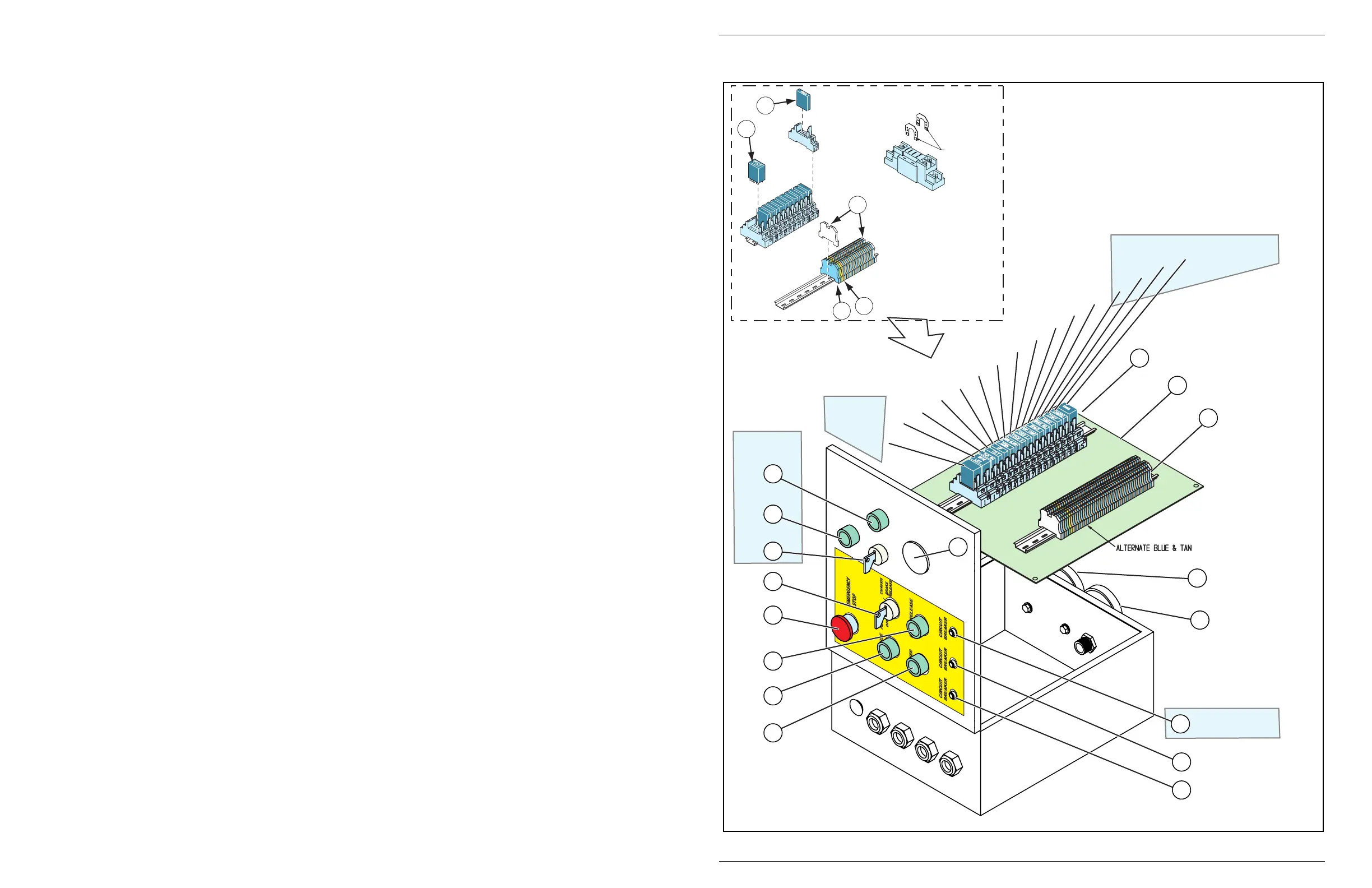
Figure 4-1:
Lower Control Box Assembly
R1
OR-R16
9
12
13
14
16
15
17
10
11
2
1
4
3
5
8
7
6
R2
R3
R4
R5
R6
R7
R8
R9
R10
R11
R12
R13
R14
R15 (S/N 4275-Up)
Bi-Energy
Outrigger
Option
Bi-Energy
Bi-Energy
S25
S27
S28
S4
S17
S5
S6
ALM1
ALM2
CB1
CB2
CB3
M1
Lower Control Box
1. Emergency Stop Button
2. 3-Position Selector Switch
(Platform/Chassis/Brake Release)
3. Raise Button
4. Brake Release Button
5. Lower Button
6. Circuit Breaker
7. Circuit Breaker
8. Circuit Breaker
9. Glow Plug Button (Bi-Energy)
10. Start Button (Bi-Energy)
11. Run/Charge Switch (Bi-Energy)
12. Hour Meter
13. Down Alarm
14. Tilt Alarm
15. Control Panel Assembly
16. Terminal Blocks
17. Relays
d
e
c
b
a
a. End Bracket
b. Terminal Block
(Blue or Tan)
c. Terminal Block Ground
(Yellow or Green)
d. Relay, DPDT
e. Relay, SPDT
Retainer Catch
to be Positioned
to the Inside
Catch Style Retainer
Latch Style
Retainer

 Loading...


