Section 4 - Schematics Component Identification
067448-023 LX31/LX41 Electric and Bi-Energy Work Platform | European Specifications Page 4-23
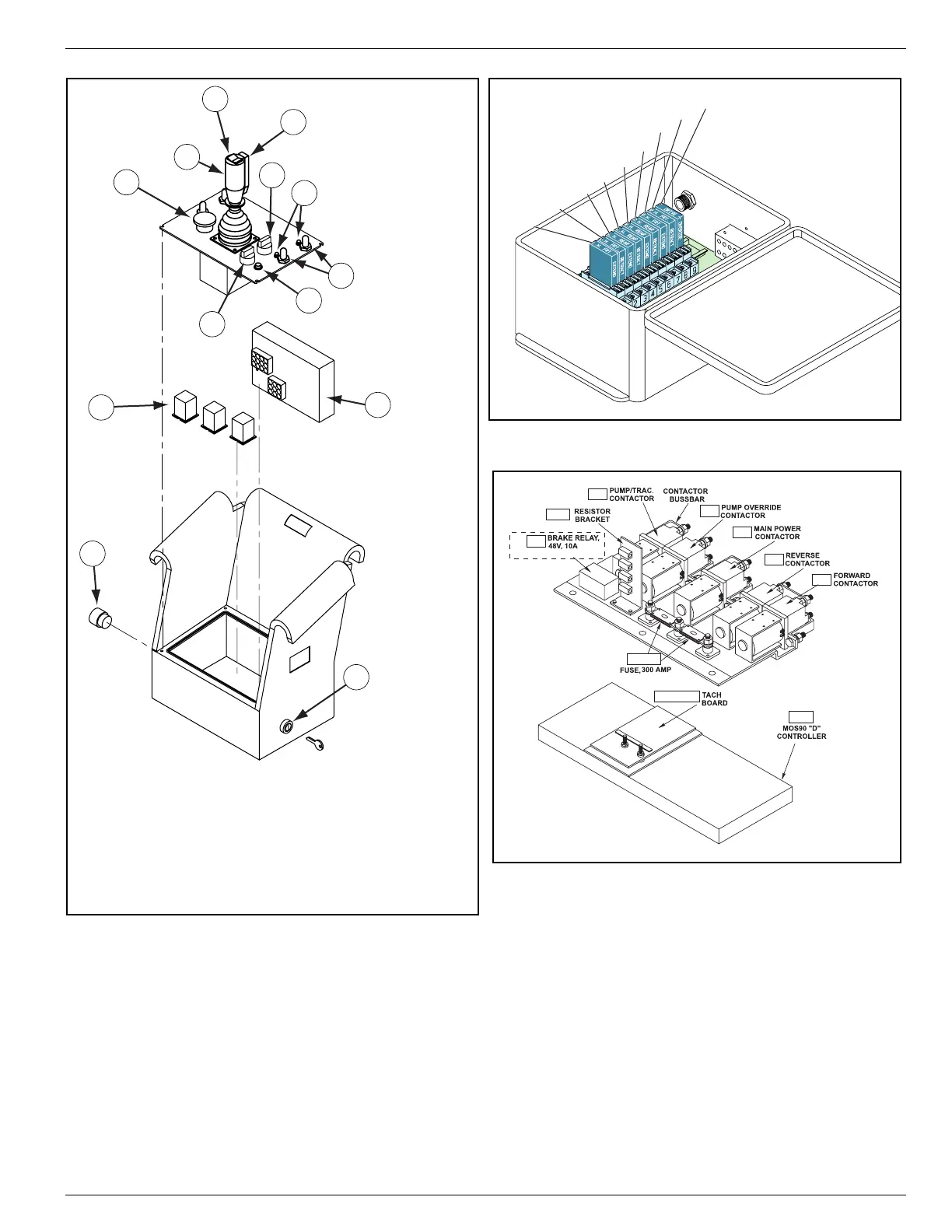
Figure 4-2:
Upper Control Box Assembly
Figure 4-3:
Outrigger Relays
Figure 4-4:
Relay Panel Assembly
10
R16
R17
OR-R18
S1
S21
S22 (Bi-Energy)
S19
S20
S18
S24
S7
L1
OR-LB
OR-L1 — OR-L4
OR-S1 — OR-S4
S9
11
13
12
Upper Control Box
1. Emergency Stop Button
2. Drive/Lift Switch
3. Speed Range Switch
4. Control Handle
5. Interlock Switch
6. Rocker Switch (Steering)
7. Drive Enable Light
8. Toggle Switch (Outriggers)
9. Indicator Lights (Outriggers)
10. Relays
11. Light Board (Outriggers)
12. Glow Plug Button (Bi-Energy)
13. Key Switch
6
4
1
5
3
9
7
8
2
OR-R9
OR-R8
OR-R7
OR-R6
OR-R5
OR-R4
OR-R3
OR-R2
OR-R1
R15
S/N 4022-4274
RES1
C5
C4
C1
C3
C2
F1&F2
TG1 & TG2
CONT

 Loading...


