4-8 X-Series Work Platform
Maintenance
Section
4.5
4.6 Switch Adjustments
TILT SENSOR (Figure 4-7)
Introduction
The Tilt Sensor has three wires; red-power (24 v in),
black-ground, white-output (24 v out). To verify the
sensor is working properly there are two LED's under
the sensor; green indicates the sensor is on (has
power), red indicates the sensor is level and the white
wire is 'hot' (24 v out).
Adjustment
1. Place machine on firm level surface ± ¼°.
2. Use the Inclinometer (P/N: 10119-000-00) to
ensure front and rear of Chassis is level ± ¼°.
3. Use the Chassis Controls to raise platform to
approximately 9.5 feet (2.9 m).
4. Install the Scissors Brace, see page 4-3.
5. Remove Tilt Sensor Electrical Box cover at front of
machine.
6. Adjust the three leveling locknuts until the bubble
is centered in the circle on the attached bubble
level.
7. Replace the Tilt Sensor Electrical Box cover.
8. Store the Scissors Brace and lower the Platform.
Figure 4-8: Tilt Sensor Adjustment
Adjusting Locknuts
Bubble Level
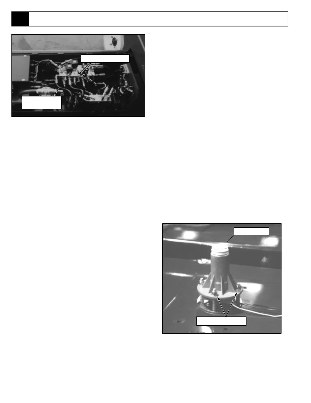
Low Side Pump
Hose
Figure 4-7: Pump Relief Valves
Pump Relief Valves
PUMP RELIEF VALVES (Figure 4-7)
1. Operate the work platform for 10-15 minutes to bring
the hydraulic oil up to normal operating temperature.
2. Move the machine, if necessary, to a location that will
allow the platform to be elevated.
3. Remove the low side pump hose from the valve
block and install the 0-6000 pressure gauge assem-
bly on the hose.
4. Turn the adjustment screw, inside the tank side of
the valve, counterclockwise two full turns.
5. Use a clean dry container or bucket (one gallon
minimum). While pointing the relief valve into the
container have another person hold the Chassis Lift
Switch to the UP position, check the gauge.
6. With the pump off turn the adjusting screw slightly
clockwise and repeat step 6 until gauge reads 3400
psi (234 bar)
maximum. Make certain the other
person does not push the Chassis Lift Switch while
the valve is being adjusted.
Note: DO NOT continue with this adjustment if more
than one gallon (3.8 l) of hydraulic oil has been
discharged into the bucket without returning it to
the hydraulic reservoir.
7. Remove the low side pump relief valve and exchange
it for the high side pump relief valve (the valve that
you just adjusted now becomes the high side relief
valve).
8. Repeat steps 5, 6, & 7 for this relief valve.
9. Replace the hose and fitting on the relief valve,
remove the gauge assembly and reinstall the hose
on the valve block and return the hydraulic oil in
the container to the hydraulic tank.
10. Operate the machine and verify it is working prop-
erly.

 Loading...


