4-14 X-Series Work Platform
Maintenance
Section
4.11
4
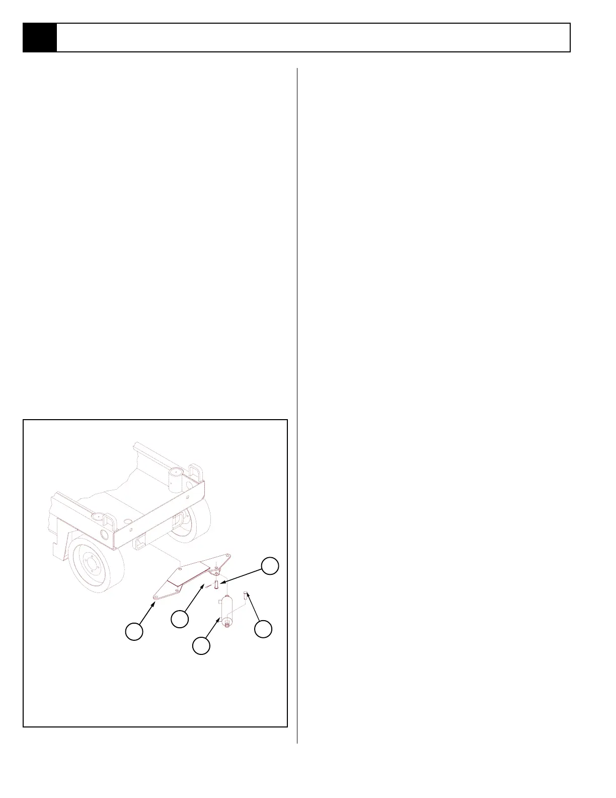
1. Steering Cylinder
2. Bell Crank
3. Rod End Pivot Pin
4. Clevis End Pivot Pin
5. Cotter Pins
Figure 4-15: Steering Cylinder Installation
4.11 Steering Cylinder
(Figure 4-15)
REMOVAL
1. Turn the wheels to the straight position.
2. Elevate the platform and block the elevating assem-
bly with the brace (see page 4-3).
3. Tag and disconnect the hose assemblies from the
cylinder fittings and immediately cap the openings
to prevent foreign material from entering.
4. Remove the cotter pins from the pivot pins.
5. Remove the pivot pins, straight up through the
Chassis, while supporting the cylinder. Remove the
cylinder.
DISASSEMBLY
1. Remove the set screw that secures the thread cap
on the cylinder barrel.
2. Unscrew the thread cap from the barrel.
2. Withdraw the head cap, piston and shaft assembly
from the barrel tube.
3. Remove the piston nut, piston and head cap.
4. Remove the rod wiper, u-cup, o-ring and backup
ring from the headcap and discard the seals.
5. Remove the internal backup rings, o-ring, and cast
iron piston seals from the piston and discard.
CLEANING AND INSPECTION
1. Wash all the metal parts in cleaning solvent and
blow dry with filtered compressed air.
2. Inspect all the threaded components for stripped or
damaged threads.
3. Check the inside surface of the cylinder barrel for
scoring or excessive wear.
4. Check the piston and headcap for scoring or exces-
sive wear.
5. Inspect the surface of the shaft for scoring or exces-
sive wear.
ASSEMBLY
1. Lubricate and install new rod wiper, u-cup, o-ring
and backup ring on the headcap.
2. Install the headcap onto the shaft.
3. Install the new internal backup rings, o-ring and
piston seal on the piston.
4. Install the piston on the shaft and secure with the
piston nut, torque to 75 Ft/Lbs (102 Nm).
5. Lubricate the piston seal with clean hydraulic fluid
and install the shaft assembly in the cylinder barrel.
6. Screw head cap into cylinder barrel until tight and
secure with set screw.
INSTALLATION
1. Position the cylinder assembly in the chassis and
insert pivot pins and secure with
new cotter pins.
2. Connect the hose assemblies to the fittings.
3. Operate the steering circuit several times throughout
its entire range of travel to expel trapped air and
check for leaks.
1
5
2
3

 Loading...


