X-Series Work Platform 4-9
Maintenance
Section
4.6
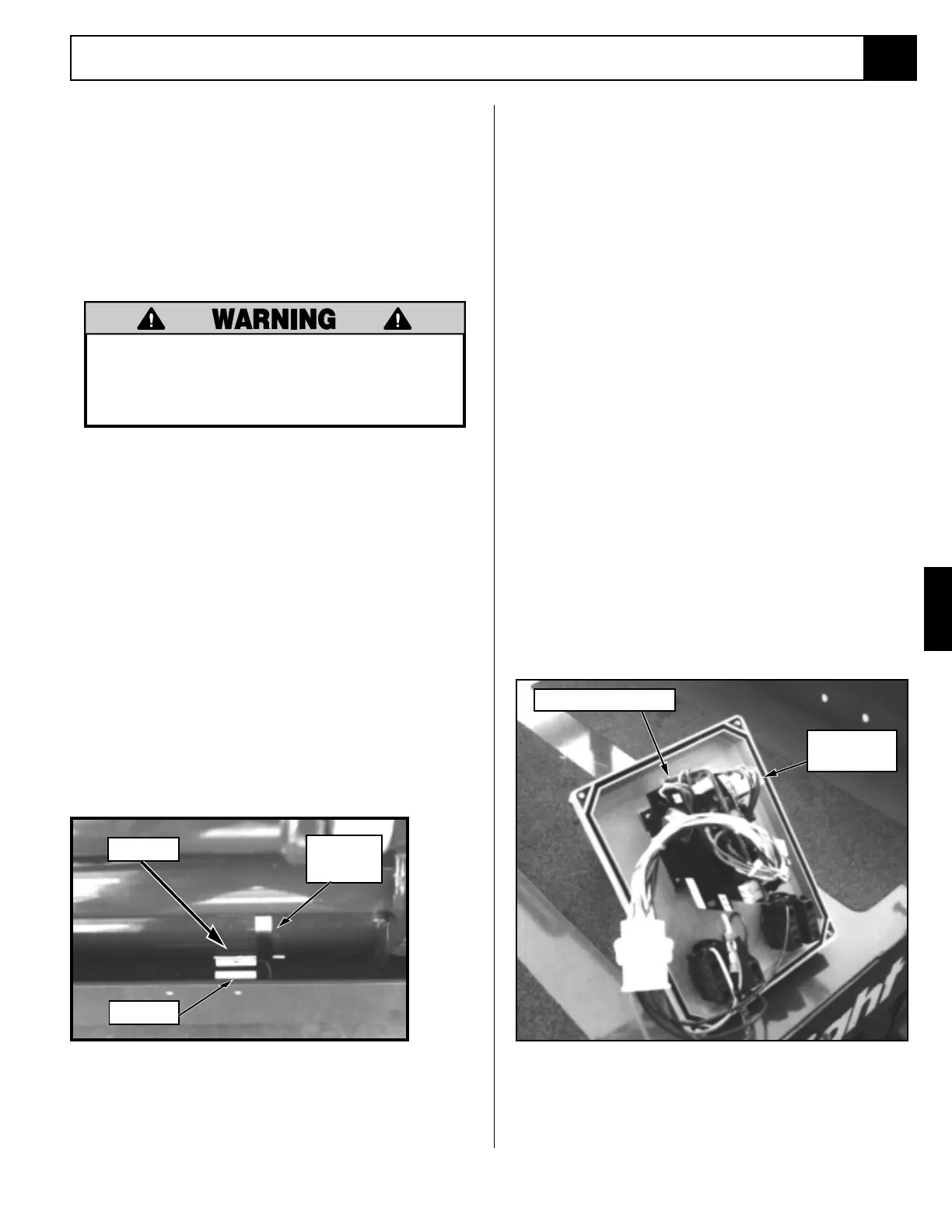
Figure 4-10: Proportional Controller Adjustment
Figure 4-9: Down Limit Switch Adjustment
Magnet
Switch
Band
Clamp
DOWN LIMIT SWITCH (Figure 4-9)
The Down Limit Switch providess power to the High
Speed Circuit when the platform is completely lowered
aand enables the Tilt Sensor/Pothole Interlock Cicuit
when the Platform is elevated. The Down Limit switch is
located on the chassis Frame at the front of the machine
near the lowest pivot tube of the Elevating Assembly.
The switched adjustment is to be preformed with the
platform completley lowered.
Always use the Elevating Assembly Brace
whenever it is necessary to enter the
elevating assembly when the Platform is
elevated.
1. The switch (mounted to the chassis frame) is acti-
vated by a magnet mounted to the elevating assem-
bly pivot tube with a band clamp). Locate these two
components.
2. Disconnect the switch wires at the control
module by unplugging the slide terminals.
3. Loosen the band clamps securing the magnet to the
pivot tube just enough to allow the magnet to
rotate. Rotate the magnet down below the switch.
4. Use a multimeter to check continuity in the switch.
The switch contacts should be "open". Slowly rotate
the magnet upward closer to the switch until the
contacts "close" and tighten the band clamp to
secure the magnet in place.
5. Connect the switch leads.
6. Elevate the platform six inches and verify
that the high speed circuit is inoperable.
If the high speed circuit is operable, the
switch is not properly aadjusted and the
above procedure must be repeated.
Optional Proportional Controller
(Figure 4-10)
To perform the adjustment the Controller (Control Box)
must be opened by removing the screws at the corners
of the Controller and rotating the top forward to expose
the proportional controller. Remove the potting mate-
rial from the LO potentiometer adjustment screw if
necessary.
Only the LO potentiometer might require adjust-
ment, DO NOT attempt to adjust the other potenti-
ometers as they are preset at the factory.
1. Select Lift with Drive/Lift Switch and elevate plat-
form 6 in. (152 mm). Assure that machine is above
Proximity Switch and in low range
2. Select Drive with Drive/Lift Switch.
3. Push Control Lever fully to forward or Reverse and
check that machine speed is 20 ft. (6.1 m) in 18-22
seconds.
4. Adjust 'LO' trim pot if required, turning clockwise
increases speed.
LO Potentiometer
OEM
Controller

 Loading...


