Schematics
X-Series Work Platform6-2
Section
6.1
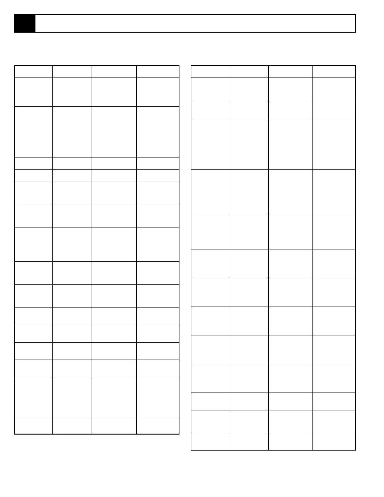
Table 6-1: Electrical Schematic Legend, X20N, X20W, X26N
REFERENCE
DESIGNATION NAME FUNCTION LOCATION
ALM1 Alarm, Down Provides warning In front of
sound (60 Hz) when electrical box
the Platform Down inside left Chassis
function is activated. Module. Red wire
for 60 Hz.
ALM2 Alarm, Platform Provides warning In front of
Tilt/Pothole sound (600 Hz) electrical box
Protection when Platform is inside left Chassis
on slopes of 2°
side
Module. White wire
to side and 2°
fore for 600 Hz.
and aft, or when the
Pothole Protection
Supports do not
deploy properly.
BAT Batteries (4) To store energy. Inside right Chassis
6 volts Module.
CB Circuit Breaker Overload protection Chassis Control
for the control circuit. Panel.
D1 Diode Allows power to R1 Left Chassis
through R3 to power module between
motor when steer A2 and Chassis
is selected. Lift Switch.
D2 Diode Allows power to R1 Left Chassis
through R3 to power module between
motor when steer A3 and Chassis
is selected. Lift Switch.
D3 Diode Provides power to In Controller
Motor Start circuit between Drive/
through Controller Lift Selector Switch
Power On Switch and S1 and S2.
from Drive/Lift Switch
when in DRIVE.
D4 Diode Prevents feedback Connected
into the Chassis Lift between terminal
Circuit from the Key A12 and the
Switch. Chassis Lift Switch.
D5 Diode Prevents feedback Connected
into the Controller between terminal
Circuit from the A12 and the
Chassis Lift Circuit. Key Switch.
D6 Diode Provides power to
On Chassis Terminal
Drive Dump Coil Strip between
from Reverse Circuit. A3 and A4.
D7 Diode Dampers spike & Connected
improves life of between A7 &
Solenoid. ground stud on R1.
D8 Diode Dampers spike & Connected
improves life of between A7 &
Solenoid. ground stud on R1.
FU1 Fuse, 175 AMP Overload protection Inside left Chassis
for the electric motor. Module on right
bulkhead.
LS1 Switch, Down Provides power to Left rear corner
Limit (Tilt/Pothole Tilt Alarm Relay of Tilt Sensor
Interlock Circuit) when Platform is electrical box:
down. Contacts 1,2,3&4;
(High Speed Cuts power to High Contacts 6,7&8.
Drive Circuit) Speed Coil when
Platform is elevated.
MOT Motor, Electric Provides power to Left Chassis
Drive Hydraulic Module.
Pump.
6.1 Electrical Schematic
REFERENCE
DESIGNATION NAME FUNCTION LOCATION
MTR Meter, Low Shows state of Battery Chassis Control
Voltage/Hour charge and hours Panel.
(Optional) machine has been
operated.
R1 Relay, Motor Connects Batteries Inside Left Chassis
Start to Motor. Module. Mounted
on right bulkhead.
R2 Relay, Drive/Lift Energized when Right hand relay in
Drive/Lift Switch Electrical Box,
is in DRIVE, provides closest to side
power to Forward where cables enter
or Reverse Coils from box.
Controller or to
Up or Down Coils
from Controller when
not energized.
R3 Relay, Tilt Alarm Energized by Tilt Left hand relay in
Sensor when level, Electrical Box,
or Down Limit farthest from side
Switch
when
Platform where cables enter
is down, provides box.
power to Motor Start
Relay or Tilt Alarm
when not energized.
R4 Relay, Pothole Energized in Drive, Inside left Chassis
Protection allows Pothole Module, mounted
Protection coils to on right bulkhead.
energize when High
Speed Drive is
activated.
R5 Relay, High Speed Energized when Inside left Chassis
Drive machine is fully Module, mounted
lowered. Allows on right bulkhead.
High Speed Drive &
disables Tilt Sensor.
S1 Switch, Joystick Supplies power to Left rear switch
Power Motor Start circuit. when top of
Controller is held
in assembled
position.
S2 Switch, Joystick Supplies power to Left front switch
Down/Reverse Motor Start circuit when top of
or Down/Reverse Controller is held
circuits. in assembled
position.
S3 Switch, Joystick Supplies power to Right rear switch
Up/Forward Up/Forward circuits. when top of
Controller is held
in assembled
position.
S4 Switch, Joystick Supplies power to Right front switch
High Speed High Speed circuit. when top of
Controller is held
in assembled
position.
S5 Switch, Chassis Control circuit Chassis Control
Emergency Stop shut off. Panel.
S6 Switch, Chassis Provides power to Chassis Control
Selector Key either the Chassis Panel.
Controls or the
Controller.
S7 Switch, Controller Control circuit Platform Controller
Emergency Stop shut off. bottom left.
Button.

 Loading...


