X-Series Work Platform
Schematics
Section
6-3
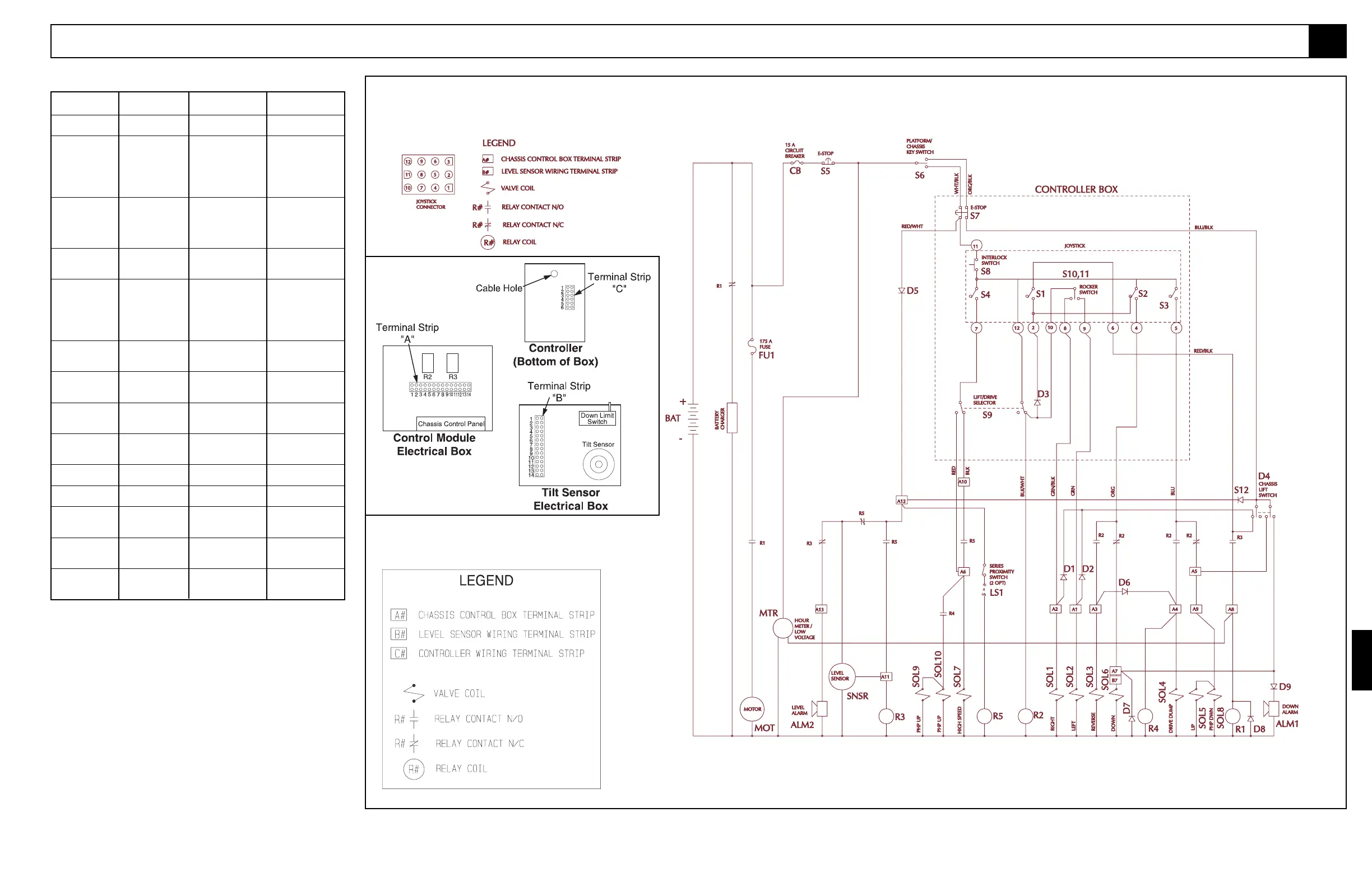
Figure 6-2: Electrical Schematic, X20N, X20W, X26N
6.1
Figure 6-1: Terminal Strip Identification
Table 6-1: (cont'd.)
REFERENCE
DESIGNATION NAME FUNCTION LOCATION
S8 Switch, Interlock Supplies power Front of joystick.
to Controller.
S9 Switch, Drive/Lift Supplies power to Controller
Selector High Speed circuit, bottom right.
and Drive/Lift Relay
and Motor Start
circuit when in
DRIVE Position.
S10 & Switches, Steering Supplies power to Rocker actuator on
S11 either Right or Left top of Controller
Steer
Valve
Solenoids. Joystick, switch
bodies inside
Joystick handle.
S12 Switch, Chassis Provides power to Chassis Control
Lift either UP or Down Panel.
circuits.
SNSR Sensor, Tilt Cuts power to Tilt Inside Tilt Sensor
Alarm Relay when Electrical Box.
Platform is on slopes
of 2° side to side and
2° fore and aft to
activate Tilt Alarm.
SOL1 Solenoid, Right Shifts Steer Valve Coil closest to
Steer (coil) to RIGHT turn block on left side
position. of Manifold Block.
SOL2 Solenoid, Left Shifts Steer Valve Coil farthest from
Steer (coil) to LEFT turn block on left side
position. of Manifold Block.
SOL3 Solenoid, Reverse Shifts Forward/ Top of Manifold
(coil) Reverse Valve to Block towards
reverse position. right side.
SOL4 Solenoid, Drive Closes Drive Dump Top center of
Dump (coil) Valve. Manifold Block
towards front.
SOL5 Solenoid, Lift Shifts Drive/Lift Valve Top center rear of
(coil) to Lift position. Manifold Block.
SOL6 Solenoid, Down Opens Down Valve. Base of Lift
(coil) Cylinder.
SOL7 Solenoid, High Shifts High Speed Top center left of
Speed (coil) Valve to High Speed Manifold Block.
position.
SOL8 Solenoid, PHP Extends Aux. Manifold
Down Pothole Cylinders block in Control
Module.
SOL9 & Solenoid, PHP Retracts On Pothole
SOL10 Up Pothole Cylinders Protection
cylinders.

 Loading...


