4-6 X-Series Work Platform
Maintenance
Section
4.5
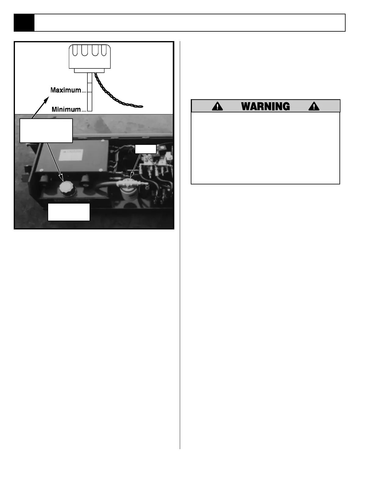
Reservoir Breather/Cap
Clean breather/cap, when filter is replaced, with clean-
ing solvent and blow dry with clean dry compressed air.
7. Release the Chassis Lift Switch. Tighten locknut or
replace Main Relief Valve cover and torque to 6 Ft/
Lbs (8 Nm.).
Figure 4-5: Hydraulic Oil Tank and Filter
Drain Plug
(Under Tank)
4.5 Setting Hydraulic Pressures
(Figure 4-5)
Check the hydraulic pressures whenever the pump,
manifold or relief valves have been serviced or
replaced.
The hydraulic oil may be of sufficient
temperature to cause burns. Wear safety
gloves and safety glasses when handling
hot oil.
The oil in the hydraulic system is under
very high pressure which can easily cause
severe cuts. Obtain medical assistance
immediately if cut by hydraulic oil.
MAIN RELIEF VALVE (Figure 4-5)
1. Operate the hydraulic system 10-15 minutes to
warm the oil.
2. Remove high pressure gauge port cap and install the
pressure gauge assembly.
3. Loosen locknut or remove cover on the Main Relief
Valve and turn adjusting screw counterclockwise
two full turns.
4. Place the maximum rated load, see
Table 1-1
, on
the platform.
5. Turn the Chassis Key Switch to CHASSIS. Position
the Chassis Lift Switch to UP position and hold it
there.
6. Slowly turn the Main Relief Valve adjusting screw
clockwise to increase the pressure until the platform
just begins to raise. Check the gauge and verify the
pressure does not exceed 2400 psi (165 bar). If it
does readjust the Main Relief Valve to 2400 psi (165
bar) maximum.
Hydraulic Tank
Breather/Cap/
Dipstick
Filter

 Loading...


