X-Series Work Platform 4-7
Maintenance
Section
4.5
STEERING RELIEF VALVE
1. Operate the work platform for 10-15 minutes to
bring the hydraulic oil up to normal operating
temperature.
2. Install gauge in low pressure gauge port.
3. Loosen locknut or remove cover on the Steering
Relief Valve and turn adjusting screw counterclock-
wise two full turns.
4. While one person holds the Steering Switch to steer
right or left, slowly turn the Steering Relief Valve
adjusting screw clockwise to increase the pressure
until the gauge reads 1500 psi (103 bar).
5. Tighten locknut or replace Steering Relief Valve
cover and torque to 6 Ft/Lbs (8 Nm).
6. Remove gauge and replace cap.
COUNTERBALANCE VALVES
(Figure 4-6)
1. Operate the work platform for 10-15 minutes to
bring the hydraulic oil up to normal operating
temperature.
2. Remove high pressure gauge port cap and install the
pressure gauge assembly.
3. Lift work platform and block chassis so front wheels
are off the ground.
4. Loosen the locknuts on Counterbalance Valves.
5. With the Chassis Key Switch on DECK and the
Drive/Lift Switch in DRIVE depress the Interlock
Lever and slowly pull the Control Lever to REVERSE
to drive the wheels.
6. Adjust the Forward Counterbalance Valve by turning
the adjustment screw until the pressure gauge
indicates 325 psi (22.4 bar).
7. Slowly push the Control Lever to FORWARD to
drive the wheels.
8. Adjust the Reverse Counterbalance Valve by turning
the adjustment screw until the pressure gauge
indicates 325 psi (22.4 bar).
9. Check the settings by slowly moving the Control
Lever FORWARD, then REVERSE checking the
gauge to ensure pressures are properly set. Readjust
as needed.
10. Tighten locknuts on valves to 6 Ft/Lbs (8 Nm).
Remove blocks and lower work platform to ground.
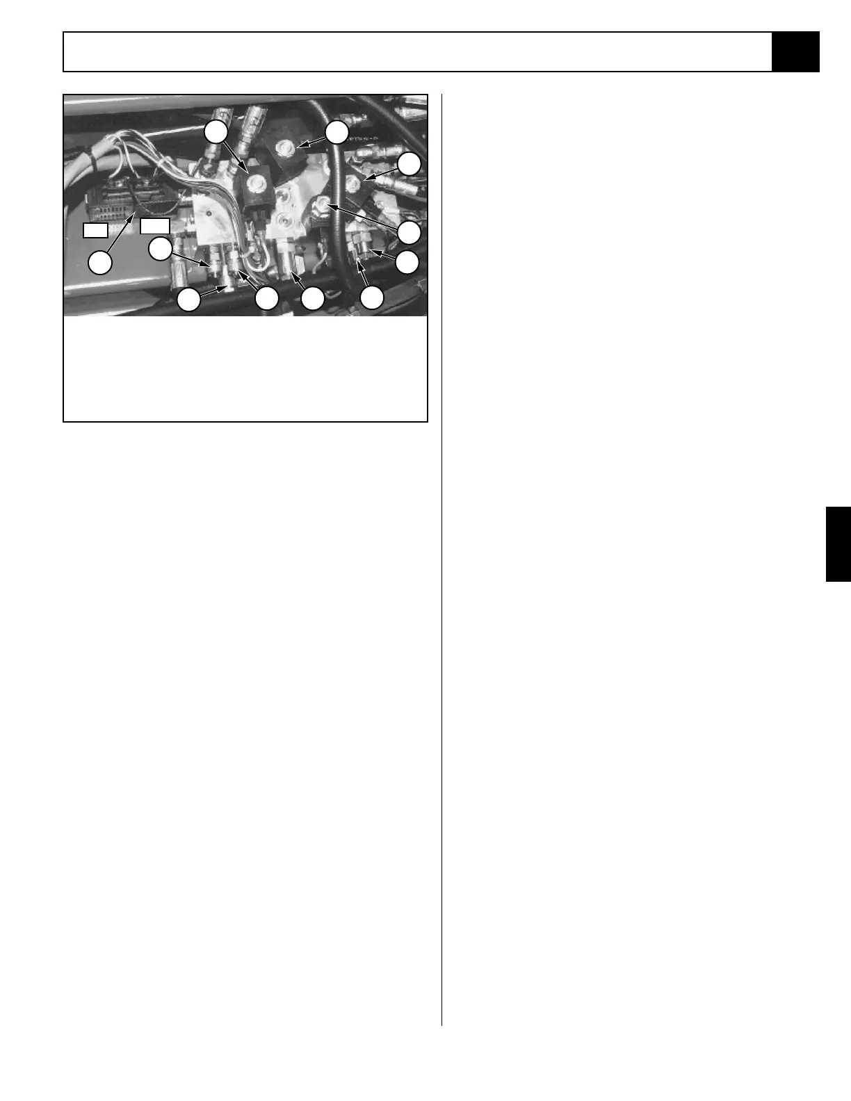
1. Main Relief
2. Steering Relief
3. Fwd. C-Balance Valve
4. Rev. C-Balance Valve
5. High Press. Gauge Port
6. Low Press. Gauge Port
7. Drive/Lift Valve
8. Steering Valve
9. High Speed Valve
10.Forward/Reverse Valve
11.Drive Dump Valve
1
2
4
5
7
8
Left
Right
6
9
10
11
3
Figure 4-6: Hydraulic Manifold

 Loading...


