4-12 X-Series Work Platform
Maintenance
Section
4.8
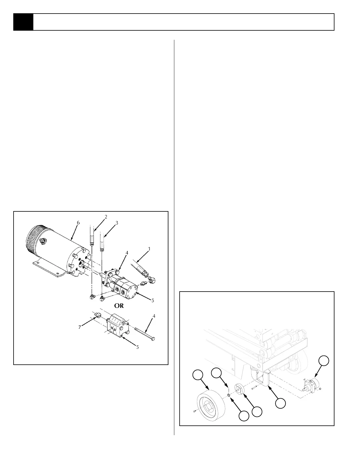
Figure 4-13: Drive Motor Installation
1
2
3
4
6
5
1. Drive Motor
2. Wheel Yoke
3. Hub
4. Wheel
5. Cotter Pin
6. Slotted Nut
4.8 Hydraulic Pump (Figure 4-12)
REMOVAL
NOTE: If the hydraulic tank has not been drained,
suitable means for plugging the hoses should be
provided to prevent excessive fluid loss.
1. Mark, disconnect and plug the hose assemblies.
2. Loosen the capscrews and remove the pump assem-
bly from the motor.
INSTALLATION
1. Lubricate the pump shaft with general purpose
grease and attach the pump to the motor with the
capscrews.
2. Using a crisscross pattern torque each capscrew a
little at a time until all capscrews are torqued to 20
Ft/Lbs (27 Nm).
3. Unplug and reconnect the hydraulic hoses.
4. Check the oil level in the hydraulic tank before
operating the work platform.
4.9 Hydraulic Drive Motors and
Hubs (Figure 4-13)
REMOVAL
1. Use a 1 ton (1000 Kg) capacity jack to raise the front
of the machine. Position blocks under the machine
to prevent the work platform from falling if the jack
fails.
2. Block the rear wheels to prevent the machine from
rolling.
3. Remove the wheel bolts and wheel.
4. Remove the cotter pin, slotted nut, hub and shaft
key.
NOTE: Before disconnecting hoses, thoroughly clean
off all outside dirt around fittings. (After disconnect-
ing hoses and before removing from vehicle,
IMME-
DIATELY plug port holes.)
5. Tag, disconnect and plug the hose assemblies to
prevent foreign material from entering.
6. Remove the locknuts, capscrews and drive motor.
INSTALLATION
1. Position the drive motor in the wheel yoke and
secure with capscrews and locknuts.
2. Install the shaft key, hub and slotted nut. Torque the
slotted nut to 140 to 160 Ft/Lbs (190-217 Nm).
Install a new cotter pin, DO NOT back-off the nut
to install the cotter pin.
1. Inlet Hose
2. Outlet Hose
3. Outlet Hose
4. Capscrew*
5. Pump Assembly
6. Electric Motor
Figure 4-12: Hydraulic Pump
* Some Pumps require only 2 mounting bolts

 Loading...


