X-Series Work Platform 4-17
Maintenance
Section
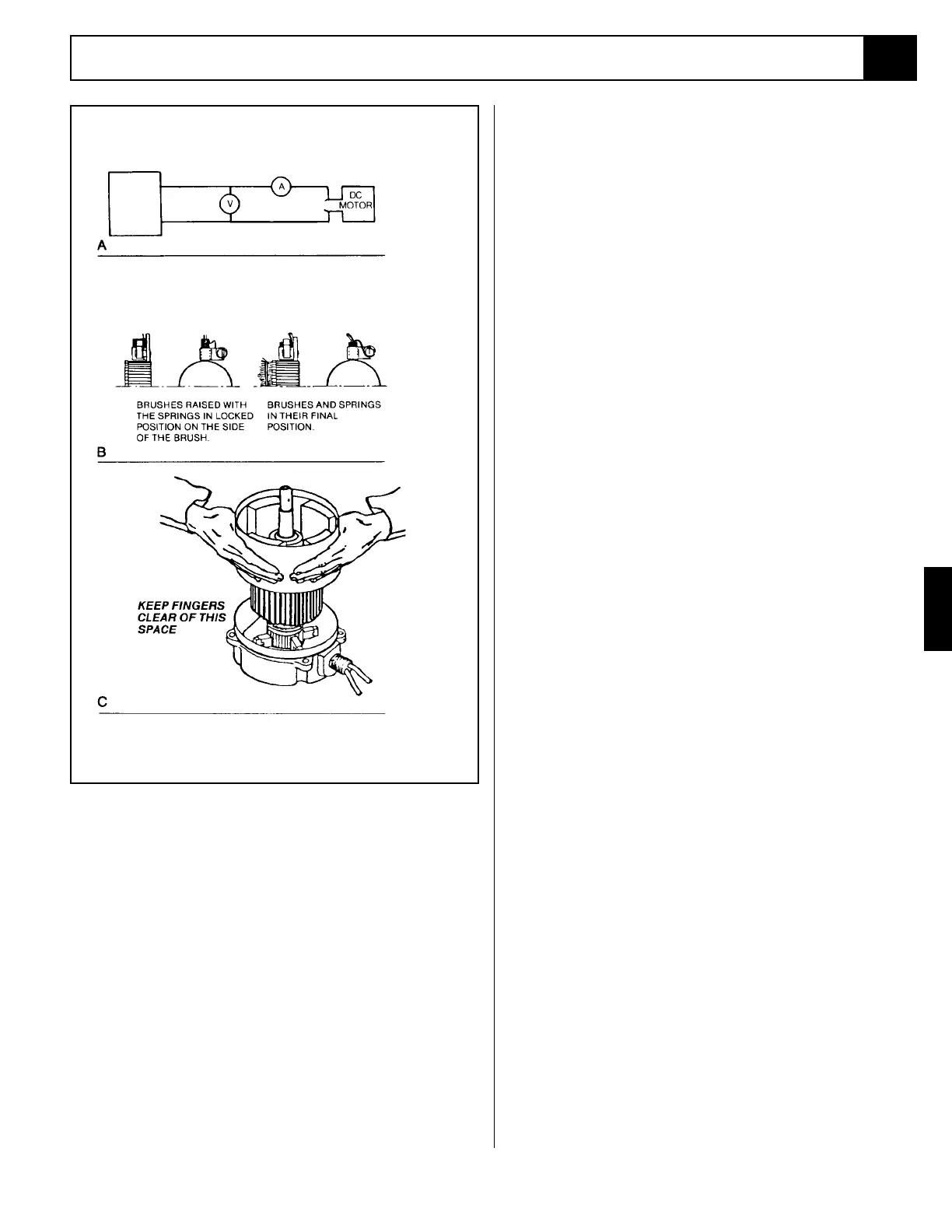
Figure 4-18: Electric Motor Service
DC
POWER
SUPPLY
AMMETER
VOLTMETER
4.13
NOTE: Observe how brushes are assembled in brush
holders and position of brush lead. New brushes
must be installed in same manner. Brushes should be
removed as follows:
•Remove brush spring clip from its mounting on
brush assembly.
•Lift brush assembly from brush holder.
•Disconnect brush assembly lead.
•New brush assembly to be installed by reversing
above procedure.
4. Inspect wire harness and all connections for signs of
damage due to overheating.
5. Check stator to see it is securely mounted.
REASSEMBLY
1. Install new brushes and be sure they are free in the
holder. Install brush with the lead wires positioned
as when received. Raise all brushes to the locked
position. (See Figure 4-18B and step 3 in the Inspec-
tion section).
2. Place commutator cover on a work bench with
brush assembly facing upward.
3. Place the bearing spring into the bearing bore.
4. Take a complete armature assembly, including
bearings, and insert commutator end bearing into
the bearing bore.
Note: Do not reuse bearings which have been re-
moved from armature shaft. Keep assembly in a
vertical position. Use extreme care not to damage
armature with bearing pullers. New bearings should
be installed by pressing inner race of bearing onto
proper position on armature shaft.
5. Set the brushes to final position as shown in Figure
4-18B.
6. Place the complete stator down over the vertical
armature, and into position on the commutator
cover.
7. The stator assembly must be placed in a definite
relationship with the commutator covers in order to
obtain a neutral brush setting. There is a match-
mark on both items. These two marks must line up
exactly. Rotate until they do.
8. Assemble the pulley end cover in the proper rela-
tionship. Insert mounting bolts and tighten alter-
nately to ensure a good mechanical alignment.
9. Spin the shaft by hand to see if it is free. Be sure
motor leads (if used) are not touching together. If
the leads are touching, a generator action will give
the effect of friction in the motor. A no-load test can
now be performed. At rated voltage, observe the
no-load current. It should be less than 20% of the
nameplate full load current. Anything higher indi-
cates:
•Brushes are not on neutral setting (check match-
marks for exact alignment).
•Faulty armature.
 Loading...


