X-Series Work Platform 4-13
Maintenance
Section
4.10
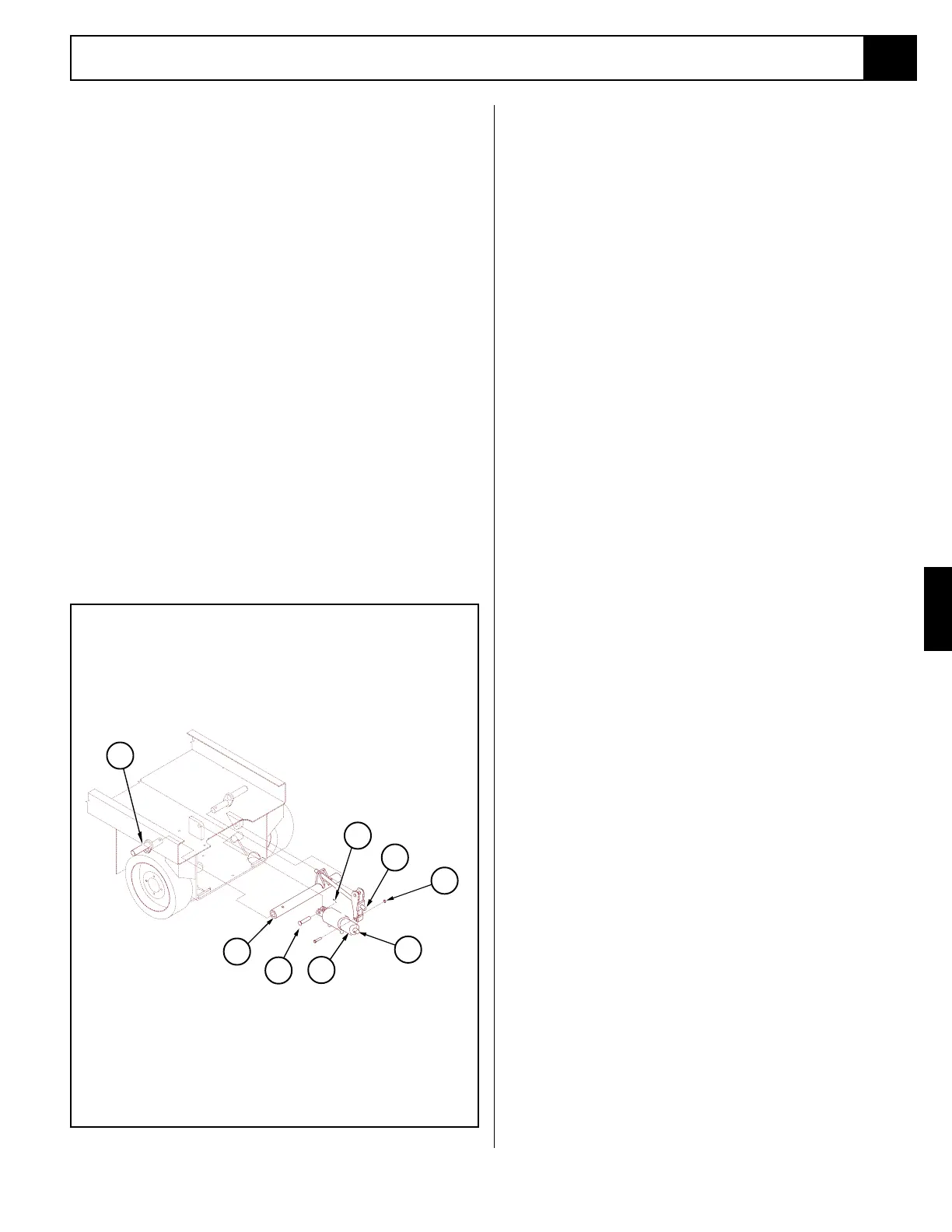
Figure 4-14: Brake Cylinder Installation
1. Brake Cylinder
2. Rod End Shoulder Bolt
3. Locknut
4. Brake Tube (shown
removed for clarity only)
5. Clevis End Pivot Pin
6. Adjustment Locknut
7. Left Brake Shoe
8. Cotter Pin
3. Remove the plugs from the hose assemblies and
connect to the drive motor.
5. Install the wheel and secure with wheel bolts,
torque to 80 Ft/Lbs (108 Nm).
6. Remove blocks, lower the jack and remove. Oper-
ate the drive system and check for leaks.
4.10 Brake Cylinder
(Figure 4-14)
The brake cylinder is located between the rear wheels
at the rear of the chassis.
REMOVAL
1. Block the wheels to prevent the work platform from
rolling when the brake is removed.
2. Remove the adjustment locknut and jam nut.
3. Tag and disconnect the hose assemblies and cap the
openings to prevent foreign material from entering.
6. Remove the shoulder bolt and locknut that mounts
the cylinder rod to the brake tube.
7. Remove the cotter pin and pivot pin from the rear
cylinder mount. Remove the cylinder.
DISASSEMBLY
1. Remove the set screw from the outside barrel
assembly and unscrew the cylinder.
2. Completely disassemble the cylinder including
removing the piston nut and piston.
3. Remove all the seals and o-rings noting their loca-
tion to aid in reassembly.
CLEANING AND INSPECTION
1. Wash all the metal parts in cleaning solvent and
blow dry with filtered compressed air.
2. Inspect all the threaded components for stripped or
damaged threads.
3. Check the inside surface of the cylinder barrel for
scoring or excessive wear.
4. Check the piston and headcap for scoring or exces-
sive wear.
5. Inspect the surface of the shaft for scoring or exces-
sive wear.
ASSEMBLY
1. Lubricate and install new seals and o-rings.
2. Install the headcap onto the shaft.
3. Install the new internal backup rings and o-rings on
the piston.
4. Install the piston on the shaft and secure with the
piston nut, torque to 250 Ft/Lbs (339 Nm).
5. Lubricate the piston seal with clean hydraulic fluid
and install the shaft assembly in the inner cylinder
barrel.
6. Install the spring and screw the cylinder barrels
together until tight and the ports are in-line.
7. Install the set screw.
INSTALLATION
1. Install the clevis end pivot pin through the cylinder
clevis and cylinder link and secure with a
new cotter
pin.
2. Install the rod end shoulder bolt through the cylin-
der rod and brake tube mounting tabs and secure
with the locknut.
3. Install the hydraulic hoses.
4. Install the adjustment locknut. Tighten the bolt until
the brake shoes fully engage the tires, secure with
the locknut.
5. Lower the machine and operate the drive circuit
and check that the brake shoes retract and clear the
tires when driving and fully engage the tires when
stopped. Check for leaks.
1
2
3
4
5
6
7
8

 Loading...


