1
4
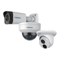
Standard Installation
Attach the wall box to the wall and use a marker to mark the location for the center
socket and the screws. Make sure the knob points down.
Figure B-10
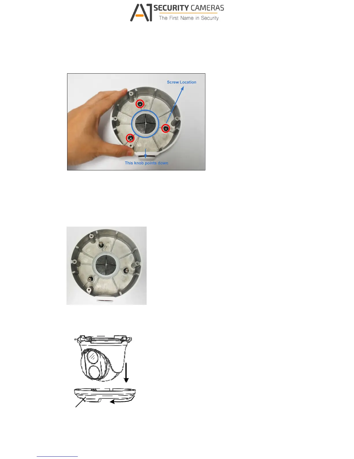
2 Drill 3 holes according to the screw location. Then, drill a bigger hole at the center
socket location for the Ethernet cable.
3 Insert 3 screw anchors to the screw location and secure the wall box to the wall with 3
long screws.
Figure B-11
Remove the bottom ring by turning it anticlockwise.
Bottom Ring
Figure B-12
 Loading...