Chapter 8 ___________________________________________________________________Repair
VAISALA______________________________________________________________________ 125
4. Loosen the hand screws to release the CLE321 board from the
frame. Carefully pull the CLE321 board halfway out of the
measurement unit and detach the battery cable (refer to number 16
in Figure 22) and the CLM311 cable (refer to number 15 in Figure
22). Then remove the entire CLE321 board. Refer to Figure 26.
0910-101
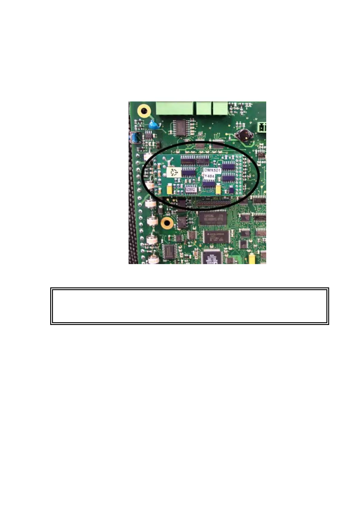
Figure 33 DMX501
WARNING
Ground yourself before touching the DMX501 module. You can do this,
for example, by touching a conductive part of the equipment chassis with
your other hand before touching the DMX501 module.
5. Pull the DMX501 module gently out of its place on the CLE321
board to avoid bending its legs.
6. Check that the legs of the new DMX501 module are straight before
placing it on the CLE321 board. Once the DMX501 module is in
its place, push it gently to the CLE321 board.
7. Place the CLE321 board onto the frame in such a way that you can
reconnect the battery cable and the CLM311 cable.
8. Reattach the receiver ribbon cable, the transmitter ribbon cable, and
the coaxial cable when the board is pushed halfway in.
9. Push the CLE321 board in such a way that it connects to the back
plane connector. Tighten the hand screws to lock the board
position.