USER'S GUIDE____________________________________________________________________
34 __________________________________________________________________ M210482EN-D
4. Close the battery cage lid and tighten the two screws to their
places.
5. Connect the no-break battery cable to the CLE321 board.
Connecting the External Cables
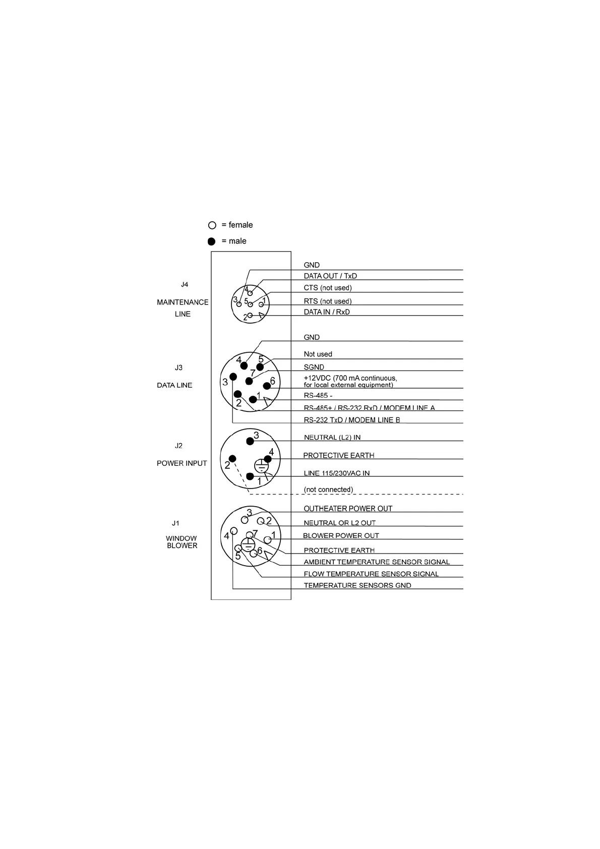
All external connectors are located at the bottom of the measurement
unit. Figure 11 shows the external connectors J1, J2, J3, and J4.
0606-210
Figure 11 External Connectors (Bottom View)
The window blower mounted into the shield is connected to J1. Line
power is connected to J2. In normal use, remote communication is
connected to J3. A local maintenance terminal, such as a laptop, can be
connected to J4. A protective cap is included for covering J4 when it is
not in use.
The power supply connector J2 provides a standard protective ground for
the instrument chassis.