USER'S GUIDE____________________________________________________________________
124 _________________________________________________________________ M210482EN-D
0910-108
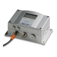
Figure 32 Modem Module DMX501
To replace Modem Module DMX501, you will need a screwdriver. As
the DMX501 module is located inside the CLE321 module, you will
have to remove the CLE321 board to get to the DMX501 module.
Proceed as follows:
1. Open the front door of the ceilometer enclosure and switch off the
power with all three switches (F1, F2, and battery). For the location
of the switches, see Figure 15 on page 40 and Figure 16 on page
41.
WARNING
Disconnect the power cable from connector J2 before continuing.
2. Detach the transmitter ribbon cable, the receiver ribbon cable, and
the coaxial cable from Ceilometer Engine Board CLE321. (Refer to
numbers 10, 4, and 3 in Figure 22 on page 104, respectively.)
3. Mem
orize the position of the data line connector (RS-232/
RS-485/Modem; refer to number 8 in Figure 22) in front of the
CLE321 board and detach it. Refer to Figure 26.