Chapter 3 ______________________________________________________ Functional Description
VAISALA _______________________________________________________________________ 21
Optical Measurements
Optical Arrangement
0403-103
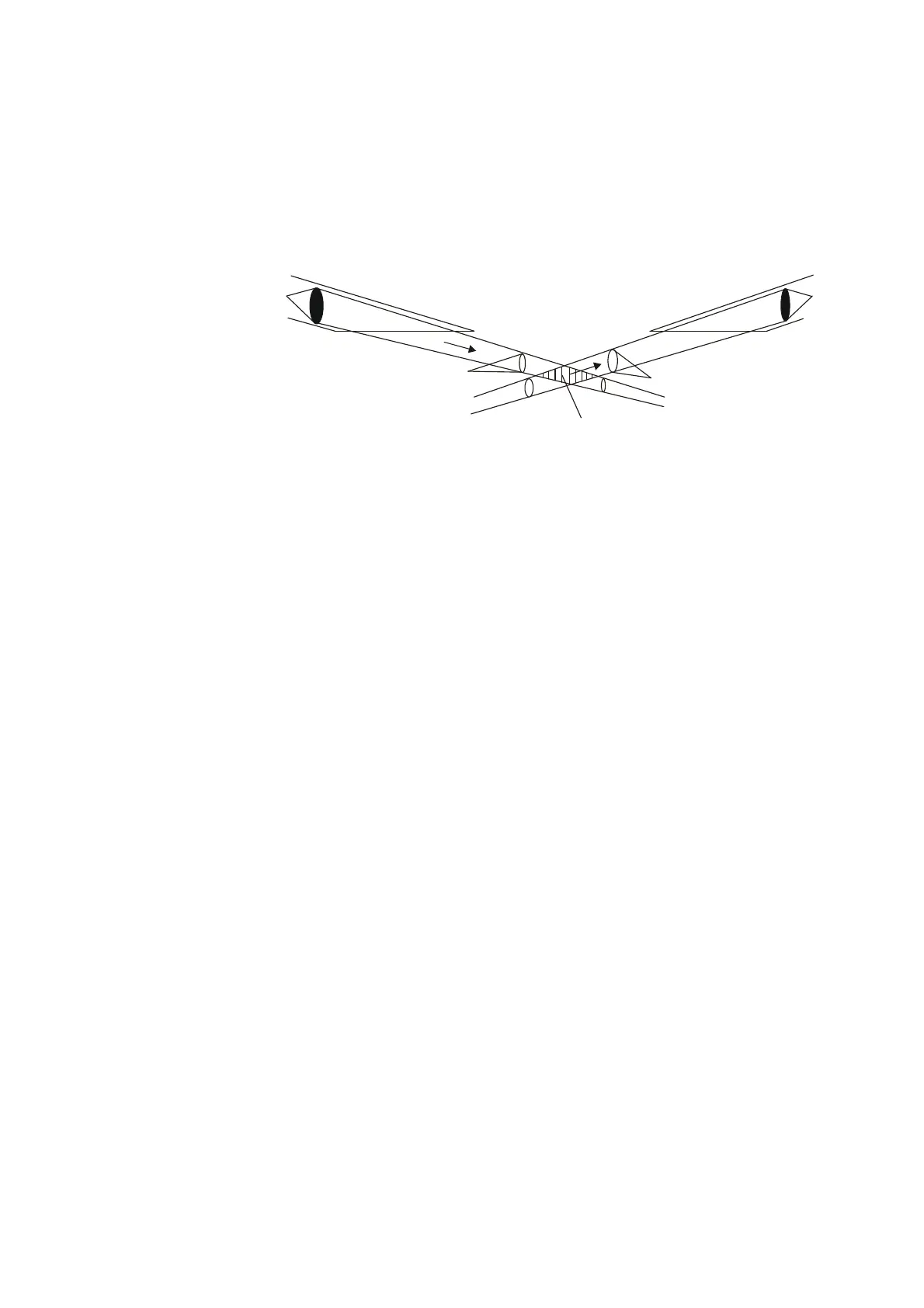
Figure 3 PWD22/52 Optical System
PWD22/52 measures light scattered at an angle of 45°. This angle
produces a stable response in various types of natural fog. Precipitation
droplets scatter light in a different manner from fog and their contribution
to visibility must be analyzed separately. PWD22/52 can detect and
measure precipitation droplets from the optical signal and use this
information in processing scatter measurement results.
PWD22/52 has a small sample volume of about 0.1 liters (see Figure 3).
This allows for independent particles to be measured at relatively heavy
precipitation intensities. The signal levels from the smallest precipitation
droplets can also be detected.
Transmitter Unit PWT11
The transmitter unit consists of an infrared LED control and triggering
circuits, LED intensity monitor, and backscatter receiver.
The transmitter unit electronics pulses the IR-LED at a frequency of
2 kHz. A PIN photodiode monitors the transmitted light intensity. The
transmitter intensity level measurement keeps the LED's intensity at a
preset value automatically. The CPU monitors the "LEDI" feedback
voltage to get information of the aging of the LED and possible defects.
The feedback loop compensates for the LED temperature and aging
effects of the LED. On the other hand, the active compensation slightly
accelerates the LED aging. The initial LED current is set to a value that
ensures several years of operation without maintenance.
An extra photodiode measures the light scattered backwards from the
lens, other objects, or contaminants. This signal is also monitored by the
CPU.
Receiver
Transmitter
Sample volume
3 cm
4 cm
 Loading...