402
REVO-E Heat pump 4 Function and functional schematics
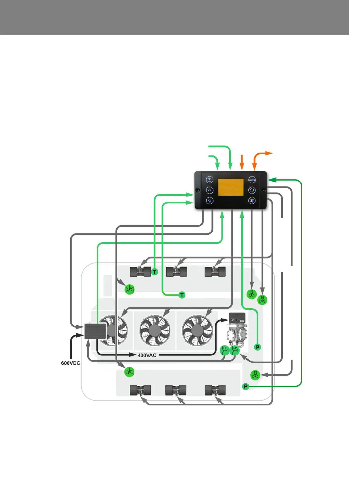
4.2 Functional schematic of the REVO-E heat pump
Tasks of the SC620
– Implementing climatic and heat pump requirements
– Turning off high-voltage components in case of error
(HVIL)
– Component protection of the climate unit if overloaded
Required to start the system:
– Power supply clamp 30 (main switch of battery)
– Ignition on (clamp 15)
– CAN communication between vehicle and SC620 ac-
tivated - approval for system start shared
– High voltage to the frequency converter, that means
high voltage system active
– Approval (D_AuxiliaryPowerEnable) and supply
Fig. 401 Functional schematic of the REVO-E
Analog input
HVIL 1 voltage
Analog input
HVIL 2 voltage
CAN interface
vehicle
SC620
Sensor
blow-out
temperature
Sensor
pass. comp.
temperature
Double radial blower
Speed
Compressor
Fresh air
flaps actuator
Double radial blower
Axial fans
Frequency
converter
Fresh air
flaps
actuator
active
Compressor activate
4
5
1
2
3
6
7
NOTE:
Details about the positions can be found in
the overview Fig. 2 in Chapter 3 of the
workshop manual.
1 Solenoid valve
2 Solenoid valve HGA / actu-
ator (in 11123865_only)
3 Suction pressure sensor
4 High pressure safety switch
5 Low pressure safety switch
(not in 11123865_)
6 4-way reversing valve
7 High pressure sensor
24V
4-way reversing valve works as actuator