410
REVO-E Heat pump 4 Function and functional schematics
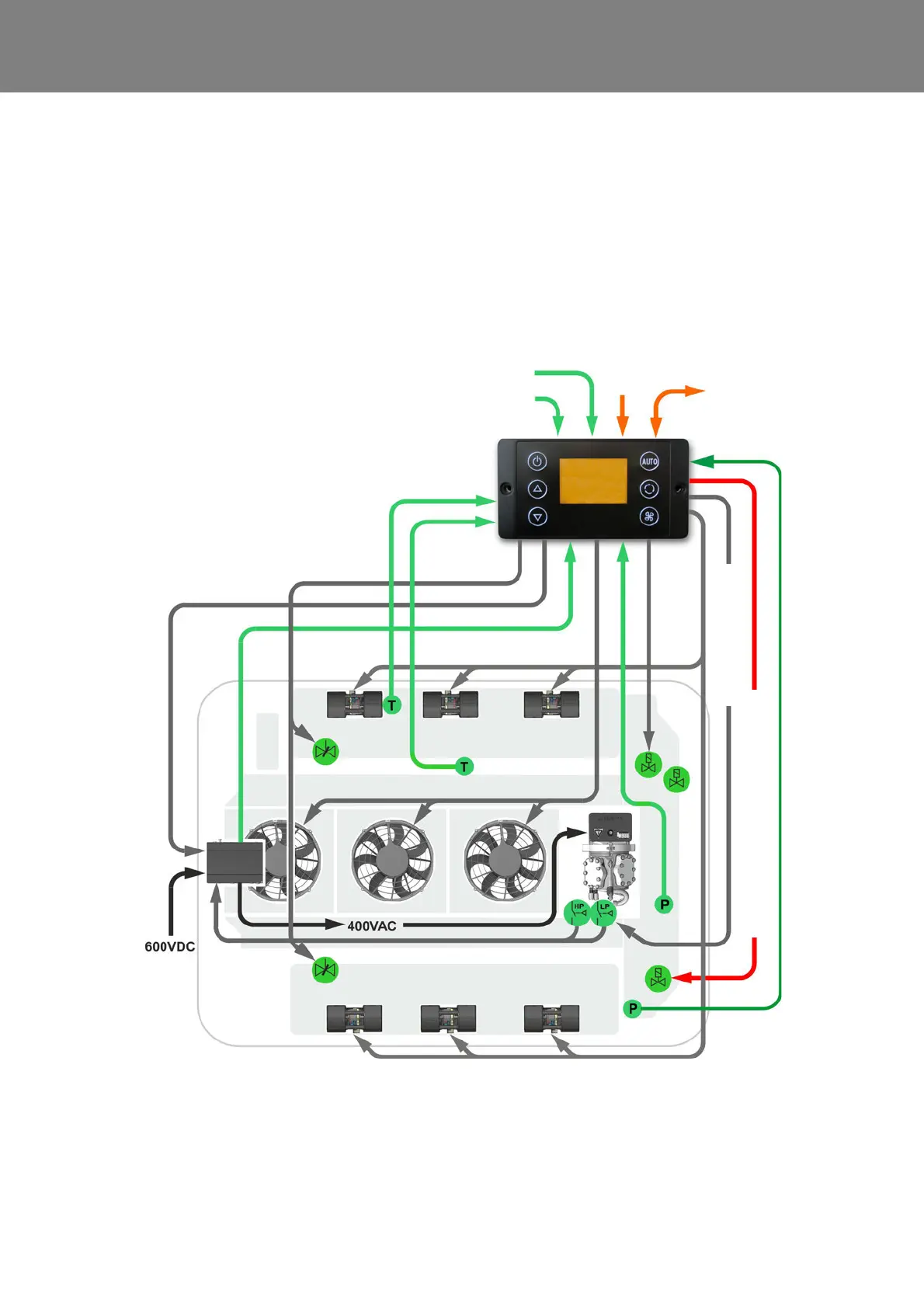
4.4.5 Heat Pump Mode
Requirements:
– Environmental temperature ≥ -5°C (11123865_)
– Environmental temperature ≥ 3°C (11120816_)
– no frequency converter or compressor errors
– no low-voltage error
– Terminal 15 active
– Vehicle hybrid system active
– HVAC power consumption enabled by
“D_AuxiliaryPowerEnabled” signal
– no HVIL error
– ∆T temperature passenger compartment > 0K
– SC620 CAN message “heat pump available“ to BEA
body
– “D_CabinHeatpumpReq” signal sent by BEA body
Fig. 407 Heat Pump Mode
Analog input
HVIL 1 voltage
Analog input
HVIL 2 voltage
CAN interface
vehicle
SC620
Sensor
blow-out
temperature
Sensor
pass. comp.
temperature
Double radial blower
Speed
Compressor
Fresh air
flaps actuator
Double radial blower
Axial fans
Frequency
converter
Fresh air
flaps
actuator
active
Compressor activate
4
5
1
2
3
6
7
1 Solenoid valve
2 Solenoid valve HGA / actu-
ator (in 11123865_only)
3 Suction pressure sensor
4 High pressure safety switch
5 Low pressure safety switch
(not in 11123865_)
6 4-way reversing valve
7 High pressure sensor
24V
4-way reversing valve works as actuator