909
REVO-E Heat pump 9 Removal/ installation of components
9.12 Pressure switch removal/ installation
There are valve inserts built into the screw neck of the
pressure switch that automatically close when the sensor
is removed from the support.
9.12.1 Remove the pressure switch
• Disconnect electric connection.
• Unscrew pressure switch, holding onto the screw-in
connector with suitable tool.
9.12.2 Install the pressure switch
• Screw in new pressure switch with new copper
sealing ring, holding onto screw-in connector with suit-
able tool.
• Reattach electric connection.
• Lay cable, making sure there are no points of abra-
sion.
9.13 Compressor suction and pressure
lines removal/ installation
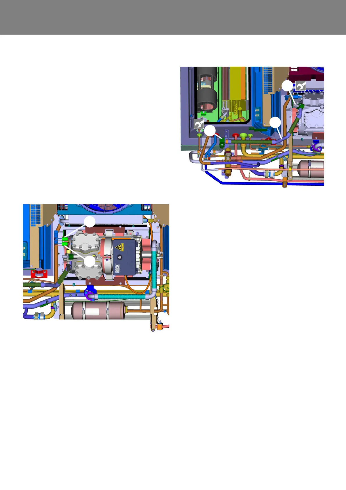
9.13.1 Remove the pressure line
• Conduct preparation work according to 9.3.
• Unscrew filler valve (2, Fig. 911) from the pressure
line.
• Disconnect the pressure line at the SMA connection
(3) from the 4-way valve.
• Disconnect the pressure line at the SMA connection
from the compressor and remove pressure line.
9.13.2 Install the pressure line
• Put pressure line including new seals (refrigerator oil
applied) into installation position and align.
• Connect pressure line onto the compressor with SMA
connection.
• Connect pressure line onto the 4-way valve with SMA
connection (3).
• Screw filler valve (2, Fig. 911) into pressure line.
• Conduct follow-up work according to 9.3.
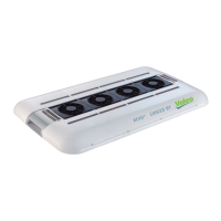
9.13.3 Remove the suction line
• Conduct preparation work according to 9.3.
• Unscrew filler valve (2, Fig. 912) from the suction line.
• Separate connections of the suction line (1) and
remove suction line.
9.13.4 Install the suction line
• Put suction line (1) including new seals (refrigerator oil
applied) into installation position and align.
• Connect both sides of the suction line.
• Screw filler valve (2) into the suction line.
• Conduct follow-up work according to 9.3.
Fig. 910
1
2
1 High pressure switch
2 Low pressure switch (not at 11123865_)
Fig. 911
1 Pressurized gas line
2 Filler valve, pressure side
3 SMA connection pressurized gas line - 4-way valve