408
REVO-E Heat pump 4 Function and functional schematics
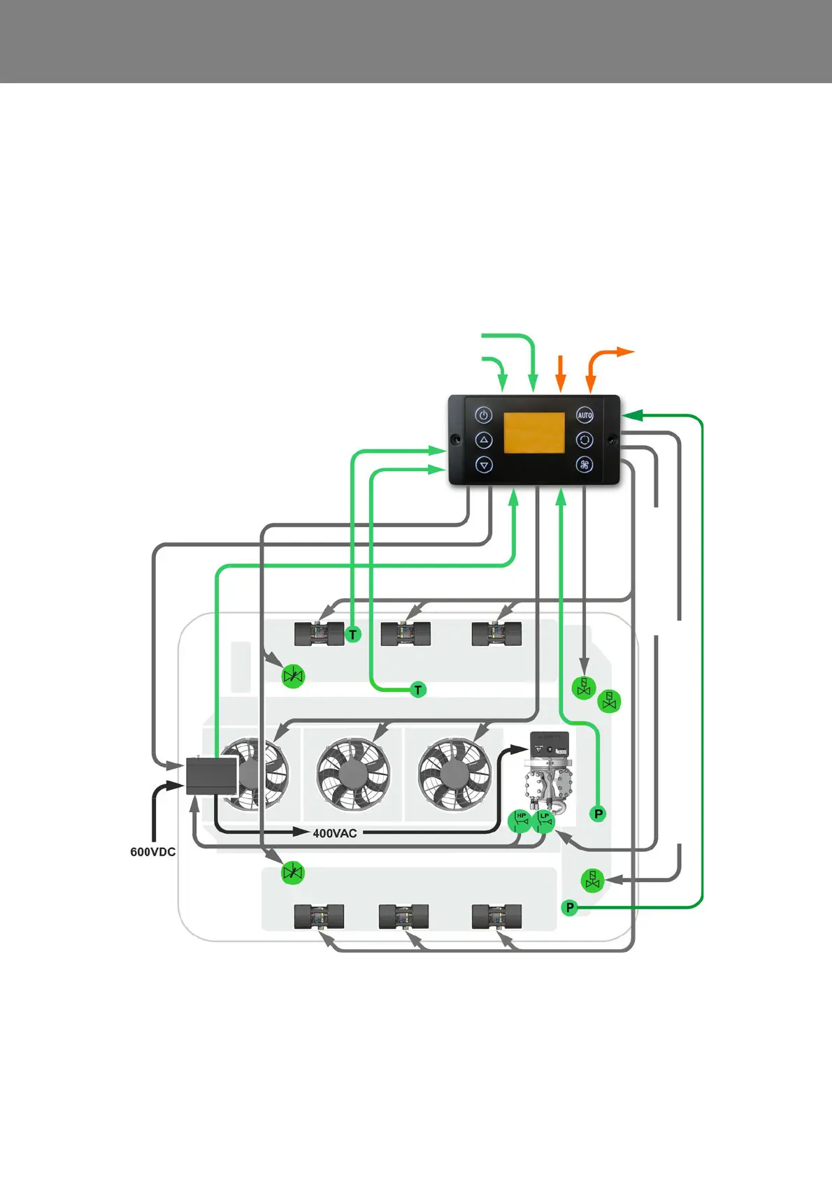
4.4.4 Cooling Mode
Requirements:
– Terminal 15 active
– Vehicle hybrid system active
– Mode “Ready for Cooling“ active
– HVAC power consumption enabled by
“D_AuxiliaryPowerEnabled” signal
– Signal “D_CabinCoolReq” sent by BEA-Body
– environmental temperature > 5°C
The Cooling Mode is requested by the BEA body system
in order to cool down the air in the passenger cabin. The
SC620 therefore assumes internal control of the compo-
nents in the system in order to cool down the air in the
passenger cabin to the Delta T value requested by the
BEA Body.
Fig. 406 Cooling Mode
Analog input
HVIL 1 voltage
Analog input
HVIL 2 voltage
CAN interface
vehicle
SC620
Sensor
blow-out
temperature
Sensor
pass. comp.
temperature
Double radial blower
Speed
Compressor
Fresh air
flaps actuator
Double radial blower
Axial fans
Frequency
converter
Fresh air
flaps
actuator
active
Compressor activate
4
5
1
2
3
6
7
1 Solenoid valve
2 Solenoid valve HGA / actu-
ator (in 11123865_only)
3 Suction pressure sensor
4 High pressure safety switch
5 Low pressure safety switch
(not in 11123865_)
6 4-way reversing valve
7 High pressure sensor
24V
4-way reversing valve works as actuator