616
REVO-E Heat pump 6 Wiring plan
6.4.2 400V AC voltage output
The PE line as well as the lines to monitor the PTC sensor of the e-motor for the compressor are integrated into this
cable in addition to the live wires.
6.4.3 PE connection (potential equalizing)
In order to guarantee a secure electrical connection when
connecting the PE line, the order of the individual parts
must be maintained (Fig. 605).
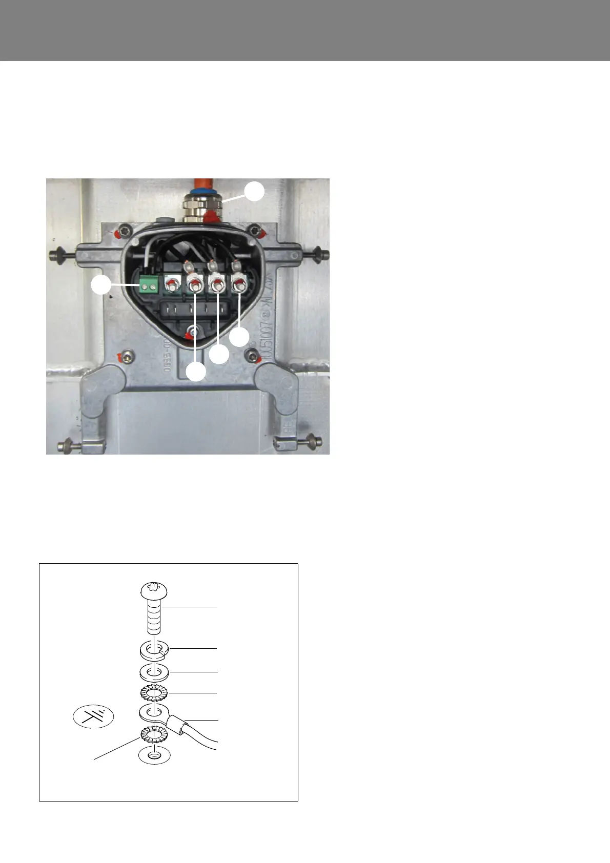
Fig. 604 Voltage output 400V AC
1 Connection for PTC sensor e-motor for
compressor
2 Cable connection for 400V AC cable
3 U – connection
4 V – connection
5 W – connection
6 PE (within connection plate)
Phase designations on the individual cables
must correspond to the designations on the
compressor (cover graphic).
U <-> U
V <-> V
W <-> W
2
1
3
4
5
Fig. 605
Screw
Spring lock
Washer
Serrated lock
Ground cable
washer
washer
Serrated lock
washer