803
REVO-E Heat pump 8 Removal/ installation of components (high-volt. syst.)
• Remove cable screw for 600V DC cable (tension
relief), remove from housing.
• Remove control lines from terminal strip of the
application board (Fig. 603).
• Remove cable screw for signal cable (tension
relief), remove from housing.
• Disconnect grounding cable from housing of
frequency converter.
• Loosen cone screw Fig. 802, Pos 5.
• Disassemble the frequency converter.
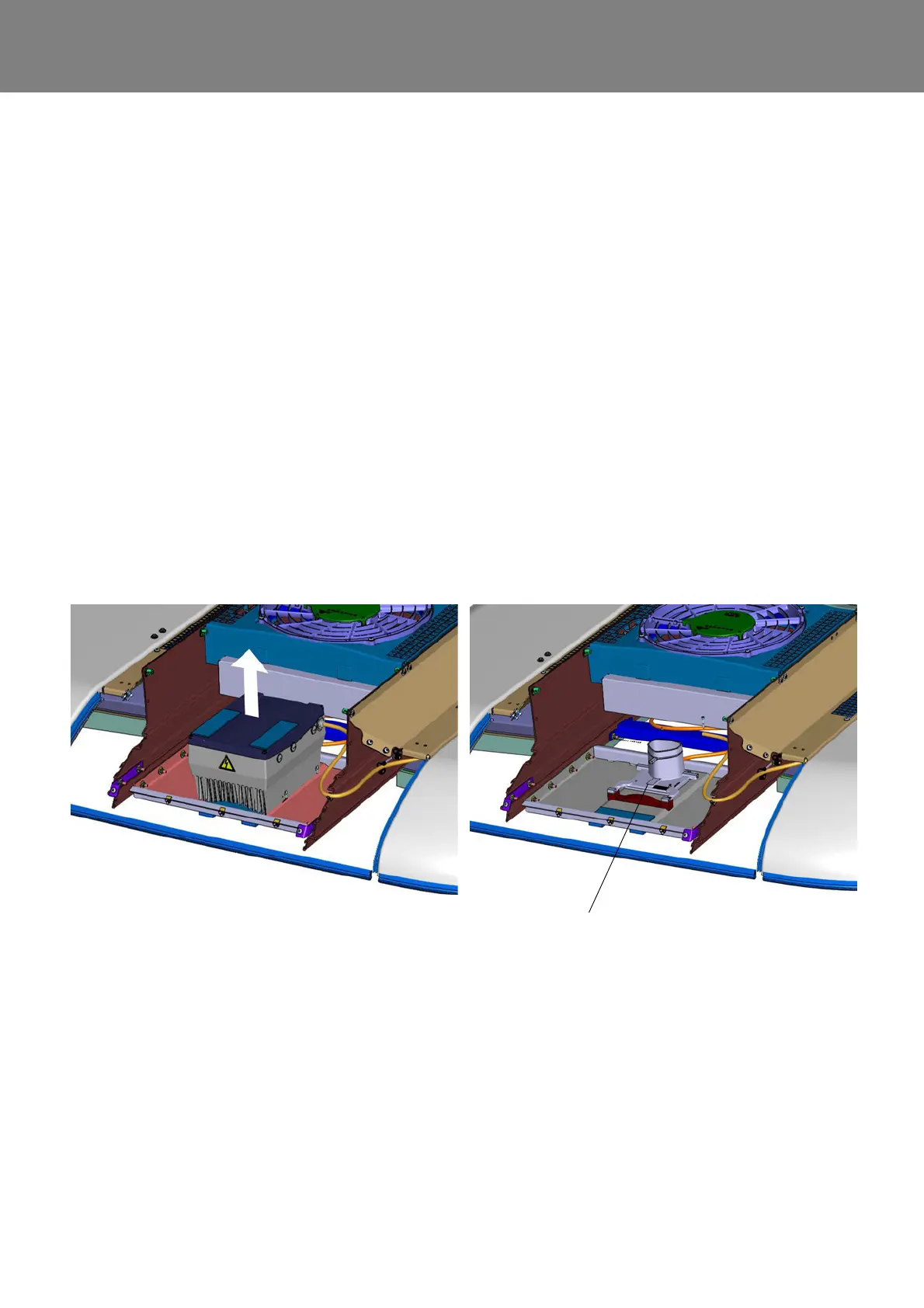
• Pull the frequency converter firmly up and off the
mounting plate (Fig. 803).
8.3.2 Install the frequency converter
• Ensure that connection terminals U / V / W (Fig. 604)
of the 400V AC cable for the mounting plate are
securely fastened.
• Set the frequency converter on the mounting plate
(Fig. 803), the collar of the plate will dip into opening
in the bottom of the heat sink of the frequency
converter.
• Inspect the positioning of the centering cone of the
fastening screws.
• Attach the frequency converter.
• Pull the control line cable into the housing and attach
cable gland.
• Connect control lines according to wiring diagram
Fig. 603 (chapter 6).
• Pull the 600V DC cable of the power supply into the
housing and attach cable gland.
• Connect power supply according to wiring diagram
Fig. 603 (chapter 6).
• Connect the HVIL plugs.
• Inspect the internal grounding cable to see if there is
contact with the cover.
• Install the cover using screws and secure it against
unauthorized access using sealing wax.
• Connect grounding cable according to Fig. 604.
• Connect diagnostic cable and tighten by hand.
• Install protective cover.
• Test functionality (using diagnostic as needed).
Fig. 803 (exemplarily)
Mounting plate of the frequency converter