901
REVO-E Heat pump 9 Removal/ installation of components
9 Removal and installation
of components
9.1 Safety information
Follow the safety information and conditions from
Chapter 1 (see 1.6 ).
The work described in the following requires proof of
the following qualifications:
See 1.6.1 under working on the refrigeration section
of the air-conditioning system.
9.2 Versions of ADA
NOTE:
Most of the work described below is identical for HP and
HP + systems. Wherever there are differences, this is
explicitly stated. The information of some graphics apply
for both versions. These graphics are marked as "exem-
plarily".
9.3 Preparation/follow-up
When working on the refrigerant circuit, the rules for evac-
uating and filling the REVO-E apply. Replace the sealing
rings from the opened connections and oil them before
replacing (refrigerator oil). If opening the conditioning
circuit is required, the following preparation and follow-up
work is required.
Preparation work
– Vehicle / air-conditioning system powered off (primary
switch / battery disconnection switch)
– If necessary, remove protective cover for the com-
pressor / frequency converter
– Open the side covers of the air-conditioning system
and prop up with rods (attached to cover)
– Remove the coil of the solenoid valve and replace with
permanent magnet
– Siphon refrigerant via high and low pressure connec-
tions on the compressor
– Close openings of components of the refrigerant
circuit with suitable plugs (presents water absorption
by the refrigerant oil)
Follow-up work
– Exchange filter dryers
– Evacuation the air-conditioning system
– Check tightness
ATTENTION:
The maximum pressure is 17 bar, the suction pres-
sure sensor will become damaged otherwise!
– Fill the air-conditioning system with R134a
– Remove the permanent magnet from the magnet
valve and install the coil
– Mount / close the cover
– Test functionality / SCT components test
Torque table, see Attachment A.
9.4 Condenser module removal/
installation
9.4.1 Removal of the condenser module
Observe the safety instructions in Cha. 8!
1. Preparation
NOTE:
The condenser module as spare part is only available as
pre-assembled unit. Replacement of individual parts is not
possible. Minimum of 2 persons is required.
• Do the preparation work according to 9.3.
2. Removal (Fig. 901)
• Protective grille (3)
• Refrigerant line collector - condenser (7)
• Pressure line compressor (5)
• Refrigerant line condenser - dryer (6)
• Disconnect electrical connections X29-2 condenser
wiring harness at terminal board (see Abb. 601,
Blatt 6).
• Remove wiring harness from clips.
• Remove the 24V wiring harness of the frequency
converter (see Cha. 8.4.1, step 1/2).
• Remove screws (4) securing the condenser
module.
• Lift out the condenser module by two persons.
• Close the openings of the refrigerant circuit and the
condenser module.
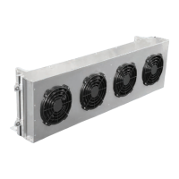
• Remove the axial fan (see 9.7.3).
• Remove the wiring harness from the condenser
module.
Potential risk to health
and life!
Warning!
High voltage!
Caution
Mortal danger!
Warning!