403
REVO-E Heat pump 4 Function and functional schematics
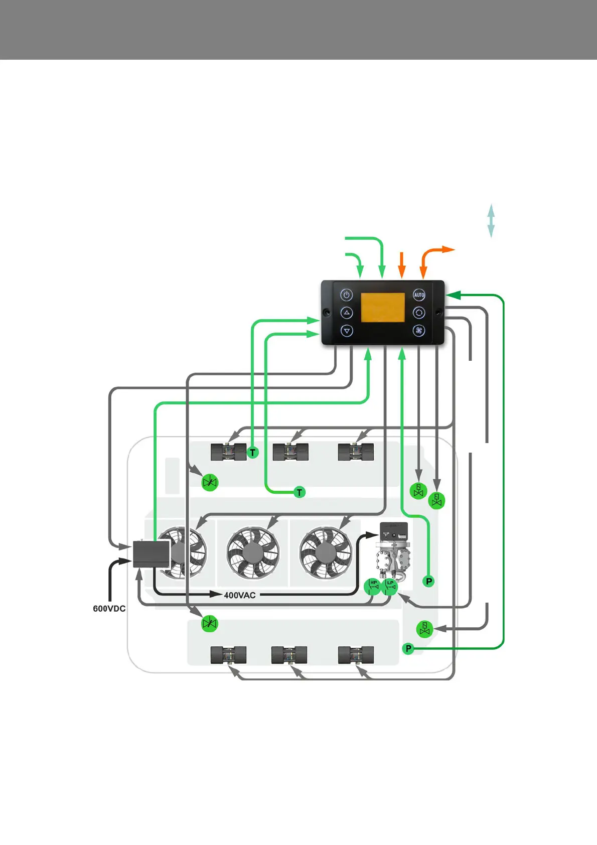
4.3 Functional schematic of the REVO-E heat pump Volvo 7900 Electric
On single buses, the ADA and SC620 are connected to
one another using a Valeo cable harness.
The HVAC control system of the BEA body system is res-
ponsible for regulating the Heating, Ventilation, Cooling
and Heat pump modes in the Volvo e-bus.
The REVO-E system therefore behaves only as a “slave”
system and implements the particular requirements.
In Heating / Ventilation or Reheat Mode, the vehicle
controller gives the speed of the double radial blowers.
In Cooling, Waste Energy or Gas Charging Mode, the
double radial blowers are controlled by the SC620.
.
Fig. 402 Functional schematic of the REVO-E, internal
Analog input
HVIL 1 voltage
Analog input
HVIL 2 voltage
CAN interface
vehicle
SC620
Sensor
blow-out
temperature
Sensor
pass. comp.
temperature
Double radial blower
Speed
Compressor
Fresh air
flaps actuator
Double radial blower
Axial fans
Frequency
converter
Fresh air
flaps
actuator
active
Compressor activate
4
5
1
2
3
6
7
1 Solenoid valve
2 Solenoid valve HGA / actu-
ator (in 11123865_only)
3 Suction pressure sensor
4 High pressure safety switch
5 Low pressure safety switch
(not in 11123865_)
6 4-way reversing valve
7 High pressure sensor
24V
D-Bus Volvo
4-way reversing valve works as actuator