617
REVO-E Heat pump 6 Wiring plan
6.5 Compressor - electrical connections
6.5.1 400V AC voltage supply
6.5.2 PE connection (potential equalizing)
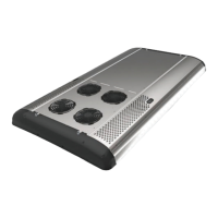
In order to guarantee a secure electrical connection when
connecting the PE line, the order of the individual parts
must be maintained (Fig. 607).
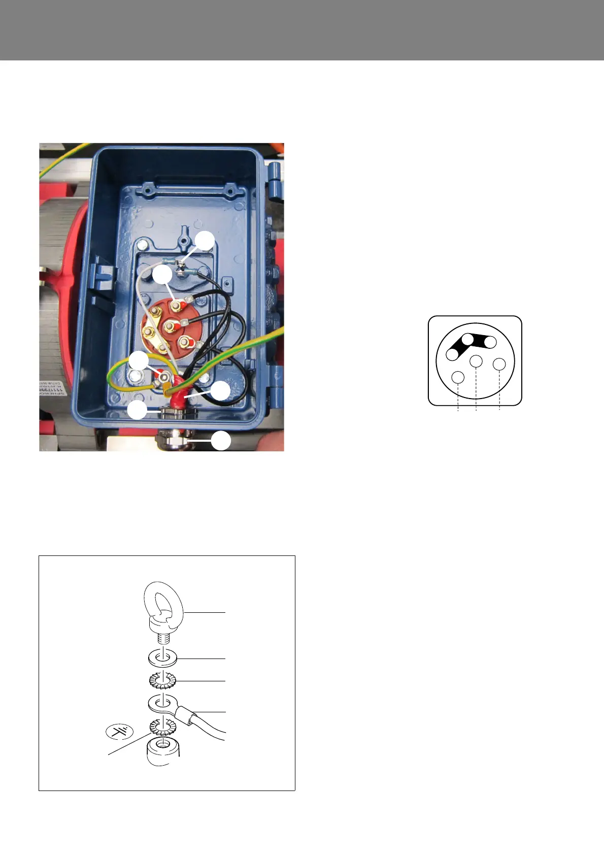
Fig. 606 Voltage supply 400V AC
1 PE connection
2 Cable gland
3 Cable gland lock nut
4 Position marking cable
5 Phase connections for 400V AC (3)
6 Connection for PTC sensor for electrical
motor
The position marking cable must be secured
with lock nut during assembly.
Phase designations on the individual cables
must correspond to the designations on the
compressor (cover graphic).
U <-> U
V <-> V
W <-> W
PE line is connected.
Cable for PTC sensor for e-motor is plugged in.
6
5
4
3
2
1
Fig. 607
Eye bolt
Washer
Ground cable
Serrated lock
washer
Serrated lock
washer