92
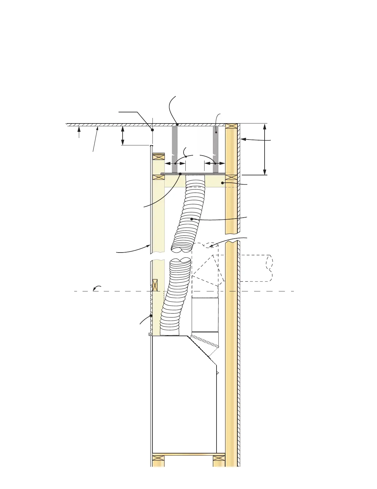
Appendix D - HeatShift System
Ceiling
2-1/2” min.
4”
See clearances
to combustibles
next page
14” min.
Minimum length
of opening,
front and sides
H5 = 40”
H6 = 50”
Combustible wall
construction
7RSRIVWDQGRV
See installation manual packed
with appliance for minimum
combustible cavity dimensions
Non-combustible
cement board
Min. 1” clearance
around pipes
2 x 4 on edge to support
plates as necessary -
maintain 1” clearance to pipes
:DOOȴQLVKUHTXLUHG
to form plenum
above duct
termination plates
LDK 7 - Duct
Termination Plates (2)
for horizontal
installation ONLY!
Continuous ceiling
UHTXLUHGZLWKLQFDYLW\
Note: Staining or streaking may
occur on light colored ceilings due
WRDQ\GXVWHWFLQDLUȵRZ
Maximizing the opening size will
help reduce any staining or
streaking.
3ODWHVWDQGR
Vertical vent can pass between
duct termination plates
Wall Valance Discharge Opening using LDK7—Duct Termination Plates