4.4 Multipulse Tune-Up Procedure (FLIPFLOP)
01-999162-00 C0402 VNMR 6.1C User Guide: Solid-State NMR
62
• Optionally
a. Type phaser=phfid, phfid='n'
b. Reacquire the spectrum.
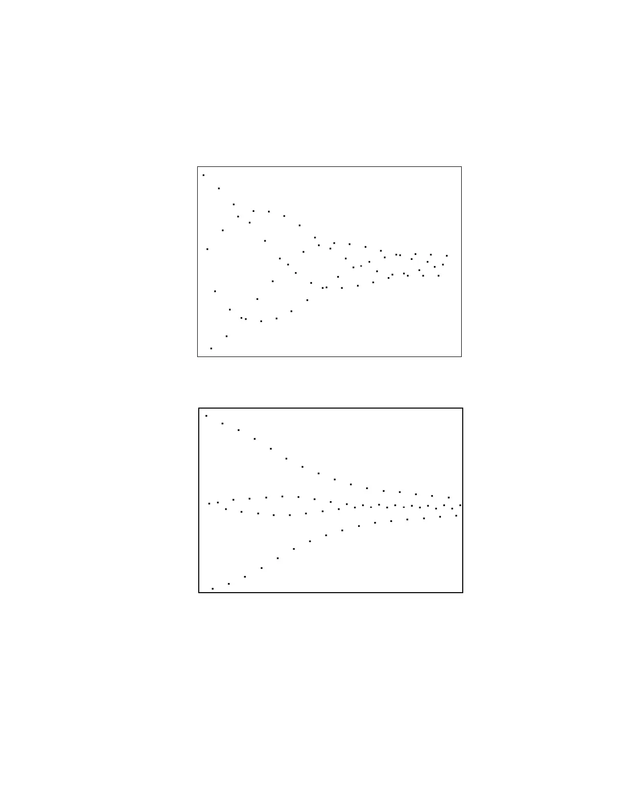
This will adjust the pulse phase to place the signal in one of the two ADC
channels. Otherwise, it usually sufficient to observe a phased display. The
real channel should appear similar to Figure 17. or Figure 18.
4. Type gf and then acqi.
5. Press the FID button and then press again to select the FID display.
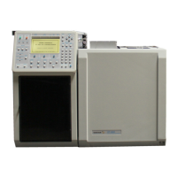
6. Press IPA and adjust the tpwrf slider to achieve a display similar to Figure 18.
The ideal signal pattern (1.0,0.0,-1.0,0.0)N results from a 90
o
pulse. The bulge
among the first few zero-points and the decay are due to RF inhomogeneity. A
distribution of pw90 values interferes to cause the pattern of Figure 18.
Figure 17. Real Channel FID Pattern
Figure 18. FLIPFLIP FID at Exact 90° Pulse